|
Page 1 of 2 Canvas provides a full transformation facility that allows you to use any co-ordinate system you want to. Alternatively you can view it as a way of drawing paths at the location and scale that you require. In this extract from a chapter in my new book on JavaScript Graphics we look at how to use transforms.
Now available as a paperback or ebook from Amazon.
JavaScript Bitmap Graphics
With Canvas

Contents
- JavaScript Graphics
- Getting Started With Canvas
- Drawing Paths
Extract: Basic Paths
Extract: SVG Paths
Extract: Bezier Curves
- Stroke and Fill
Extract: Stroke Properties
Extract: Fill and Holes
Extract: Gradient & Pattern Fills
- Transformations
Extract: Transformations
Extract: Custom Coordinates
Extract Graphics State
- Text
Extract: Text, Typography & SVG
Extract: Unicode
- Clipping, Compositing and Effects
Extract: Clipping & Basic Compositing
- Generating Bitmaps
Extract: Introduction To Bitmaps
Extract : Animation
- WebWorkers & OffscreenCanvas
Extract: Web Workers
Extract: OffscreenCanvas
- Bit Manipulation In JavaScript
Extract: Bit Manipulation
- Typed Arrays
Extract: Typed Arrays
- Files, blobs, URLs & Fetch
Extract: Blobs & Files
Extract: Read/Writing Local Files
Extract: Fetch API **NEW!
- Image Processing
Extract: ImageData
Extract:The Filter API
- 3D WebGL
Extract: WebGL 3D
- 2D WebGL
Extract: WebGL Convolutions
So far we have been working with the default co-ordinate system that, apart from antialiasing concerns, is a pixel co-ordinate system. Canvas provides a full transformation facility that allows you to use any co-ordinate system you want to. Alternatively you can view it as a way of drawing paths at the location and scale that you require.
Transformations
The drawing context has a transformation matrix associated with it and every pair of co-ordinates is multiplied by this matrix before drawing occurs.
When the context is created the matrix is set to the identity, which means you are drawing using the default pixel co-ordinates. However, there is a set of methods that can be used to set the transform to anything you like.
A general transformation takes the form:

The values of a, c, b and d specify a rotation, a scaling or a skew depending on their values. The values e and f specify a shift of the origin to the new location e,f.
This is all you need to know, but to understand the way that these transformations are presented is it worth knowing about homogeneous co‑ordinates.
The transformation can be written in matrix form as:

where in terms of the previous transformation values we have:

Notice that the rotation/scale/skew part of the transformation can be written as a matrix multiplication, but the translation is untidy in that we have to add another vector.
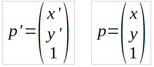
The whole transformation can be written as a single matrix multiplication if we add an extra dummy dimension, set to 1, that we simply ignore when actually drawing. That is, the transformation can be written in homogeneous co-ordinates as:

where

and

So now you know that homogeneous co-ordinates are just a trick that let us treat translation, along with rotation, etc, as part of a matrix multiplication.
This is how the canvas transformation works - you specify a 3x3 matrix in homogeneous co-ordinates - which is used to multiple the co-ordinates you specify before any drawing operation.
Now to return to the details of the programming. We have a method:
setTransform(a,b,c,d,e,f)
which sets the transformation to the matrix specified, and a method:
transform(a,b,c,d,e,f)
which multiplies the existing transformation matrix by the one specified.
Notice that multiplying transformations together effectively applies them one after another. If you want to reset the transformation use:
setTransform(1,0,0,1,0,0)
Transformation Functions
Setting the transformation in this general way is powerful, but also a bit abstract and difficult. To make things easier we also have:
-
scale(x,y) which applies a scaling in the x and y direction to the transformation matrix
-
rotate(angle) which applies a rotation angle in the clockwise direction; the angle is measured in radians
-
translate(x,y) which performs a translation by x,y.
Notice that each of these multiplies the existing transformation matrix and so this allows the transformations to be applied one after the other. So:
ctx.rotate(Math.Pi());
ctx.translate(10,10);
first rotates the co-ordinate system and then translates it.
If you already know how matrices and transformation matrices work, this will be seem quite straightforward. If not, there are a lot of traps waiting to trip you up. The main one, that troubles just about everyone at first, is that the order in which you do things matters. A translation followed by a rotation isn't the same thing as a rotation followed by a translation. Try it if you don't believe me.
Another is that these transformations change the co-ordinate system and don't affect anything you have already drawn. They only change what happens when you draw something after the transformation has been applied.
For example, to draw a rectangle and rotate and draw another rectangle:
ctx.setTransform(1,0,0,1,0,0);
ctx.fillRect (0, 0, 50, 50);
ctx.rotate(Math.PI/4);
ctx.fillRect (200, 50, 50, 50);
In this case there is a 45 degree rotation, PI/4 in radians, after the first rectangle has been drawn and before the second is drawn. The result is that the first rectangle stays where it was but the second is rotated:

After the rotation, everything you draw will be at 45 degrees. Notice that the rotation is about the origin, i.e. 0,0 which is the top left corner. This also means that the second rectangle is not at 200,50 in the co‑ordinate system of the first rectangle.
|


