|
Page 1 of 2 How do you make two GPIO lines change state at exactly the same time - not aproximately but exactly? It isn't as difficult as it sounds but it does take us beyond the IDF. This is an extract from Harry Fairhead's book on programming the ESP32 using C and the Espressif IDF.
By Harry Fairhead
Available as a softback, hardback and kindle from Amazon
Contents
Preface
- The ESP32 – Before We Begin
- Getting Started
- Getting Started With The GPIO
- Simple Output
Extract: Phased Pulses ***NEW!
- Some Electronics
- Simple Input
- Advanced Input – Interrupts
- Pulse Width Modulation
Extract: PWM First Example
- The Motor Control PWM
Extact: MCPWM First Example
- Controlling Motors And Servos
- Getting Started With The SPI Bus
- Using Analog Sensors
- Using The I2C Bus
- One-Wire Protocols
Extract: The S3's RGB LED
- The Serial Port
- Using WiFi
Extract:Socket Web Client
- Direct To The Hardware
- Free RTOS
<ASIN:1871962919>
<ASIN:187196282X>
In chapter but not in this extract
- Basic GPIO Functions
- How Fast?
- Including Pauses
- Microsecond Timer
- Fixed Time Delay
- The Interrupt Problem
Phased Pulses
As a simple example of using the output functions, let’s try to write a short program that pulses two lines high and then low, out of phase.
The simplest program to do this job is:
#include <stdio.h>
#include "driver/gpio.h"
#include "freertos/FreeRTOS.h"
#include "esp_rom_sys.h"
void app_main(void)
{

     gpio_reset_pin(2);
     gpio_set_direction(2, GPIO_MODE_OUTPUT);

     gpio_reset_pin(4);
     gpio_set_direction(4, GPIO_MODE_OUTPUT);
     while (1) {
      gpio_set_level(2, 1);
      gpio_set_level(4, 0);
      gpio_set_level(2, 0);
      gpio_set_level(4, 1);
    }
}
There is no delay in the loop so the pulses are produced at the fastest possible speed and when GPIO2 goes high GPIO4 goes low and vice versa.
Using a logic analyzer reveals that the result isn't what you might expect:
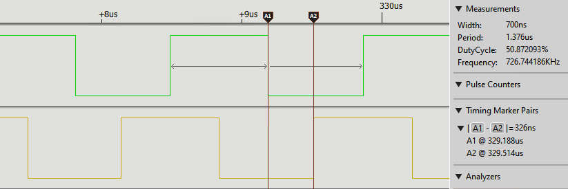
Although the intent is for both actions to occur at the same time, the top train switches on and the bottom train takes about half a pulse before it switches off.
The point is that it does take quite a long time to access and change the state of an output line. If we include a delay to increase the pulse width then the delay caused by accessing the GPIO lines in two separate actions isn't so obvious, but it is still there. There are applications where the switching speed is so low that the delay between switching doesn’t matter – flashing LEDs for instance. With a delay of around 5 µs you could flash a line of around 2000 LEDs before the lag between the first and the last became apparent. On the other hand, if you use out-of-phase pulses to control a motor, then the overlap when both GPIO lines were on would burn out the drivers quite quickly. Of course, any sensible, cautious, engineer wouldn't feed a motor control bridge from two independently generated pulse trains unless they were guaranteed not to switch both sides of the bridge on at the same time.
|