|
Page 1 of 4 The ESP32 S3 has two PWM generators - a simple one aimed at driving LEDs and a more complex one designed to make motor control easy. To get you started using it we consider a simple example. This is an extract from Harry Fairhead's latest book, Programming the ESP32 Using C and the Espressif IoT Development Framework.
By Harry Fairhead

Available as a softback, hardback and kindle from Amazon
Contents
Preface
- The ESP32 – Before We Begin
- Getting Started
- Getting Started With The GPIO
- Simple Output
Extract: Phased Pulses ***NEW!
- Some Electronics
- Simple Input
- Advanced Input – Interrupts
- Pulse Width Modulation
Extract: PWM First Example
- The Motor Control PWM
Extact: MCPWM First Example
- Controlling Motors And Servos
- Getting Started With The SPI Bus
- Using Analog Sensors
- Using The I2C Bus
- One-Wire Protocols
Extract: The S3's RGB LED
- The Serial Port
- Using WiFi
Extract:Socket Web Client
- Direct To The Hardware
- Free RTOS
<ASIN:1871962919>
<ASIN:187196282X>
The Motor Control PWM
The motor control pulse width modulation facility, MCPWM, is much more flexible than the LED pulse width modulation covered in the previous chapter, but this makes it harder to get started with. It has many features that you probably don’t want to use at first and it can be difficult to understand its basic operation. To make things easier, we can ignore many of the more advanced modules in the MCPWM and only work with the minimum needed to get started.
Many of the simpler things that the MCPWM can do can also be done using the LED PWM system. Indeed, if you want hardware fade then the LED PWM is your only choice. The MCPWM has a lot of special features that make it possible to generate multiple PWM signals with fairly complex phase relationships which are needed to drive motors and for general signaling. It also provides facilities to synchronize PWM with outside sources, react to error states by braking the motor and inserting deadtime into multiphase PWM to drive bridge circuits.
ESP32 MCPWM
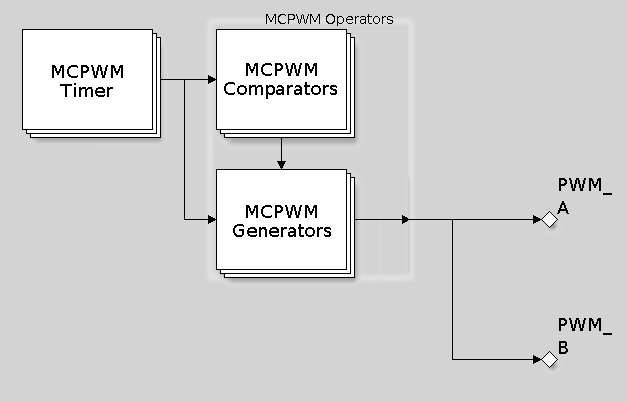
At first you only need to concentrate on the basic structure of a MCPWM configured to produce a simple PWM signal:

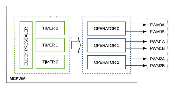
There are two complete MCPWM systems and each one has three timers and three operators each controlling two outputs, A and B, making a total of three pairs of outputs. Each pair works with the same timer and so runs at the same frequency, but they can differ in duty cycle and phase. The operator contains all of the additional modules that can change the output, including a single comparator.

The timer is the core of the system and it counts down or up or alternately up and down. It can generate events when it reaches zero or its high value. The comparator associated with the generator can raise an event when the count reaches a set value. The generators can change the state of either output on the basis of the events received from the timer or the comparator. For example, the generator could be set up to toggle one of the outputs each time the timer count reached zero and this would produce a basic PWM signal, or it could set one line high on a zero event and low on a max count event.
There are three types of timer event:
-
MCPWM_TIMER_EVENT_EMPTY Timer counts to zero
-
MCPWM_TIMER_EVENT_FULL Timer counts to peak
-
MCPWM_TIMER_EVENT_INVALID Should never happen
There is also a comparator event:
In response to an event the generator can perform any of four actions:
-
MCPWM_GEN_ACTION_KEEP Keep the same level
-
MCPWM_GEN_ACTION_LOW Force to low level
-
MCPWM_GEN_ACTION_HIGH Force to high level
-
MCPWM_GEN_ACTION_TOGGLE Toggle level
You can see that there are multiple ways of generating a signal. For example, you could set two timer events and toggle the output on zero and peak, or you could set a single timer event and set the output high on zero and a comparator event to set the output low when the count is reached, and so on. The important point to notice is that, while you have a choice how to generate a given PWM signal, exactly how you do it alters its phase relationship with other generated PWM signals. This can seem complicated so initially we will focus on generating a single PWM signal without worrying about phase issues.
|


