| Getting started with 3D XNA |
| Written by David Conrad | ||||||||
| Friday, 30 July 2010 | ||||||||
Page 2 of 7
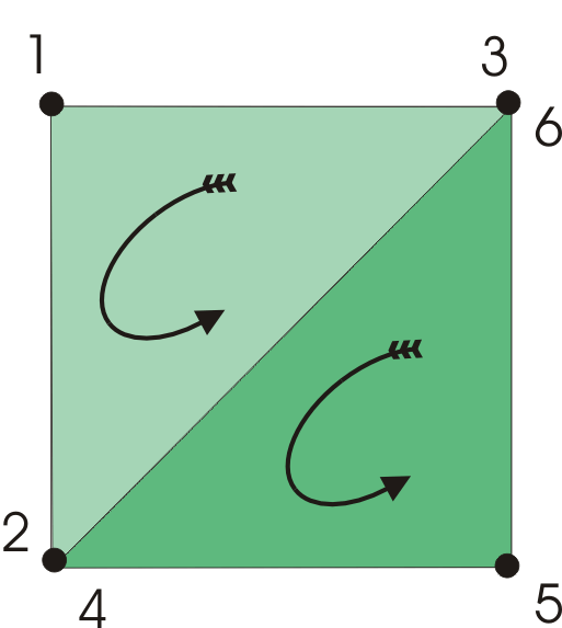
The cubeThe first thing we need is to create the geometry of the cube. There are a number of ways of defining 3D model geometry but it all comes down to defining triangles.

Each triangle has three vertexes and has a clockwise and an anticlockwise face according to the order in which the vertexes are listed. To create a square face we need to define two triangles.
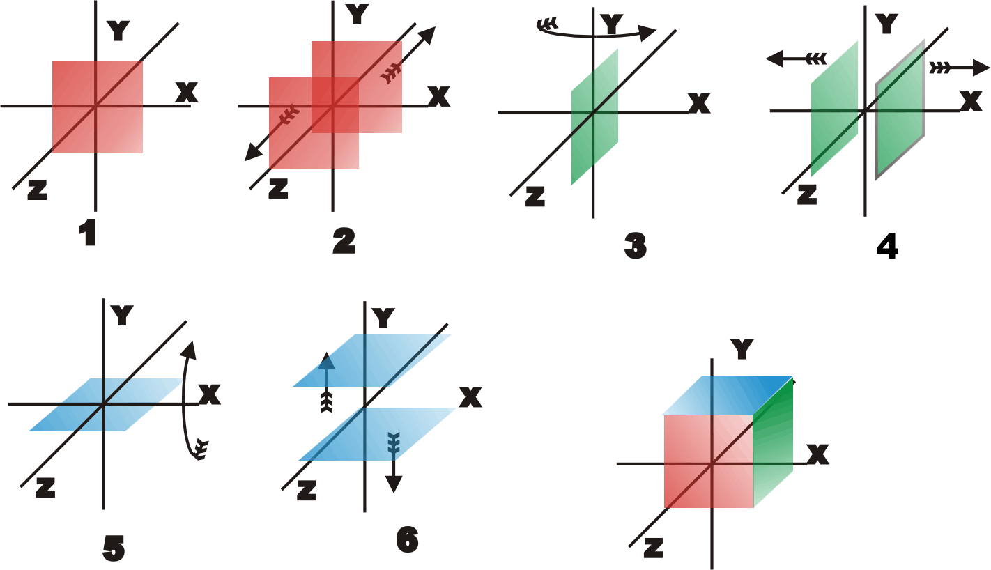
A single cube face consists of two triangles - the order of the vertexes gives each face an anti-clockwise sense. To create a cube we need six faces and hence a total of 12 triangles and 36 vertexes. Creating the data needed to define a cube isn’t difficult, but you have to get it exactly right. We are going to create a function called MakeCube which returns an array of vertexes that define the triangles that make it up. This can be done simply by entering the coordinates for each vertex and many people do use this method - it's simple and direct but it' s alot of typing. In order to reduce the amount of typing we can make use of symmetries of the cube. If you define a square face centred on the origin then a cube can be constructed by moving the face and rotating it – see the figure below:
Building a cube by defining a face and then moving and rotating it to build up the cube. The function starts off by defining an array to hold the 36 vertexes we are about to create: protected VertexPositionNormalTexture[] XNA allows the use of a range of different vertex types according to what sort of data is stored. The simplest is VertexPositionColor which stores the position of each vertex and its color. In our example the vertex type is VertexPositionNormalTexture rather than something simpler because this is what the default renderer uses. As its name suggests, this type of vertex stores the position; the normal to the surface, i.e. the direction at right angles to the surface; and a texture coordinate.The basic idea is that the normal allows lighting calculations to be performed quickly and the texture coordinate allows a bitmap texture to be mapped onto the surface. A texture is a bitmap that is normalised to use u,v co-ordinates that are in the range 0 to 1. Texture bitmaps are mapped onto the surfaces defined by the triangles and you specify texture co-ordinates for each vertex giving the position within the bitmap to be used for that vertex. We aren’t going to use the texture feature at the moment, for simplicity, but it still has to be set to a value which again for simplicity is (0,0) : Vector2 Texcoords = new Vector2(0f, 0f);We now need to code the positions of the six points that make up the two triangles that represent a face: Vector3[] face = new Vector3[6]; This slightly wasteful repeated storing of the points makes the logic of constructing the cube much easier because reading the array in sequence gives the two triangles with the vertexes in anticlockwise order. Notice also that the face is defined at z=0 and centered on the origin.
<ASIN:0123750792> <ASIN:0240814304> <ASIN:0321712617> <ASIN:0470584467> <ASIN:1430231262> <ASIN:0123751039> <ASIN:1430272058> |
||||||||
| Last Updated ( Friday, 30 July 2010 ) |