| Micro:bit - Basic PWM |
| Written by Harry Fairhead | |||||||
| Tuesday, 05 April 2022 | |||||||
Page 3 of 3
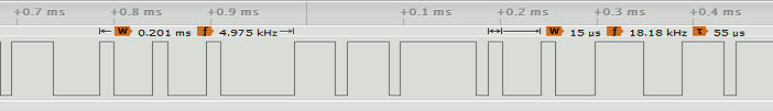
How Fast Can You Modulate?In most cases the whole point is to vary the duty cycle or the period of the pulse train, for reasons that will be discussed later. This means that the next question is how fast can you change the characteristic of a PWM line? In other words, how fast can you change the duty cycle? There is no easy way to give an exact answer and in most applications an exact answer isn't of much value. The reason is that for a PWM signal to convey information it generally has to deliver a number of complete cycles with a given duty cycle because of the way pulses are often averaged in applications. We also have another problem - synchronization. There is no way to swap from one duty cycle to another exactly when a complete duty cycle has just finished. This means that there is going to be a glitch when you switch from one duty cycle to another. Of course, this glitch becomes less important as you slow the rate of duty cycle change and exactly what is usable depends on the application. For example if you try changing the duty cycle about every 100ms and the pulse width is 50ms then you are going to see roughly two to three pulses per duty cycle: #include "MicroBit.h"
MicroBit uBit;
int main()
{
volatile int i;
uBit.init();
uBit.io.P0.setAnalogValue(200);
uBit.io.P0.setAnalogPeriodUs(50);
for (;;)
{
for (i = 1; i < 100; i++){};
uBit.io.P0.setAnalogValue(200);
for (i = 1; i < 100; i++){};
uBit.io.P0.setAnalogValue(800);
}
}
The timing of the change and the time it takes to make the change cause the glitches between duty cycles.
Is there anything that can be done about the glitching? Yes and no. You can't do anything about the 40ms or so it takes to change from one duty cycle to another, but you can synchronize when it happens to the timer using the wait_us function. If you swap the busy waits for the 100µs delays to: wait_us(100); with the help of: #define wait_us system_timer_wait_us for the V2, you will find that you do consistently get three pulses of each duty cycle, but separated by a longer pulse. What all this is really about is trying to lower your expectation of how sophisticated you can be in using PWM on the micro:bit. The fastest PWM repetition rate that you can use with the V1 is about 30ms and to minimize the glitches you need to leave the duty cycle stable for 10 to 20 pulses, i.e. about 200-600ms. In many applications this is very acceptable, but don't expect to use PWM to send coded data, and using it for waveform synthesis as a D to A converter is limited to around 4kHz. In Book but not in this extract
Summary
Micro:bit IoT In C Second EditionBy Harry Fairhead
Buy from Amazon. Contents
To be informed about new articles on I Programmer, sign up for our weekly newsletter, subscribe to the RSS feed and follow us on Twitter, Facebook or Linkedin. 
Comments
or email your comment to: comments@i-programmer.info |
|||||||
| Last Updated ( Tuesday, 05 April 2022 ) |