| Micro:bit - Basic PWM |
| Written by Harry Fairhead | ||||||||||||||||||
| Tuesday, 05 April 2022 | ||||||||||||||||||
Page 2 of 3
PWM FunctionsThe micro:bit framework attempts to provide PWM in easy-to-use forms. It provides functions which target the two main uses of PWM – D-to-A conversion and controlling servo motors. More about both topics later in the chapter. Instead of letting you specify a repeat rate and duty cycle, the framework provides two sets of functions, one for working with an analog output and one for working with a servo. Of the two, the analog output functions are the simpler and more direct. The more complex servo functions are described later in connection with implementing a servo driver. You can set the repeat period using either: int setAnalogPeriod(int period) int setAnalogPeriodUs(int period) The first sets the period in milliseconds and the second works in microseconds. The next function sets the duty cycle, but not in an obvious way: int setAnalogValue(int value) The value can be anything between 0, corresponding to a duty cycle of 0%, and 1023, corresponding to 100%. There is one small detail that you have to be aware of. The setAnalogValue function also sets up the pin for analog output, if it isn't already set up. What this means is that you have to set an analog value before you set an analog period. There are also two utility functions that let you read the current set period: int getAnalogPeriod(int period) int getAnalogPeriodUs(int period) Although you can set the repeat rate down to 1µs, the PWM mechanism in the micro:bit V1 has a smallest time of around 27µs and the timer tick is 4µs, making this the maximum achievable precision. The micro:bit V2 is fairly accurate (to within 0.1µs).
The longest time you can set is around 262 milliseconds, corresponding to the longest time a 32-bit timer running at 4µs per tick can count to. You could get different maximum and minimum rates by programming the timer yourself, but this is a difficult problem. Using PWMSo now you know how to make use of the PWM lines. All you have to do is set the value and the period. The simplest PWM program you can write is: #include "MicroBit.h"
MicroBit uBit;
int main() {
uBit.init();
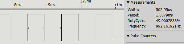
uBit.io.P0.setAnalogValue(511);
This produces a pulse train consisting of a millisecond wide pulse with a 50% duty cycle, i.e. high for 500ms.
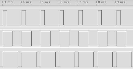
You have to set the value first and then set the period, otherwise the PWM line isn't set up properly. You also have to set the period for each pin you are using, even if it does set the same period. Notice that there is no need to put the program into an infinite loop. Once the PWM line has been set up and enabled it just gets on with generating the pulse train, no matter what the micro:bit does. In this case the pulse generation continues long after the program has ended. Just to demonstrate that multiple PWM lines can be used independently of one another, here is a program that sets each one of the three main PWM GPIO lines, P0, P1 and P2, to a different duty cycle: #include "MicroBit.h"
MicroBit uBit;
int main() {
uBit.init();
uBit.io.P0.setAnalogValue(200);
uBit.io.P1.setAnalogValue(511);
uBit.io.P2.setAnalogValue(800);
uBit.io.P0.setAnalogPeriod(1);
uBit.io.P1.setAnalogPeriod(1);
uBit.io.P2.setAnalogPeriod(1);
release_fiber();
return 0;
}
|
||||||||||||||||||
| Last Updated ( Tuesday, 05 April 2022 ) |