| Programming The ESP32 In C - PWM First Example |
| Written by Harry Fairhead | ||||||
| Wednesday, 05 February 2025 | ||||||
Page 4 of 5
A First ExampleSetting up a PWM is very simple in theory, but there are a lot of settings in the two structs involved in the configuration. The simplest example is just to generate a PWM signal on a single GPIO line. First we set up the timer: void app_main(void)
{
ledc_timer_config_t ledc_timer = {
.speed_mode = LEDC_LOW_SPEED_MODE,
.timer_num = 0,
.duty_resolution = LEDC_TIMER_13_BIT,
.freq_hz = 4000,
.clk_cfg = LEDC_APB_CLK
};
This selects low-speed timer 0 and sets its counter to 13-bit mode, which counts up to 8,191 before overflowing. The specification of a frequency of 4000Hz and a clock of 80MHz, makes the divider set to 20,000. Next we set up the channel: ledc_channel_config_t ledc_channel = {
.speed_mode = LEDC_LOW_SPEED_MODE,
.channel = 0,
.timer_sel = 0,
.intr_type = LEDC_INTR_DISABLE,
.gpio_num = 2,
.duty = 4096,
.hpoint = 0
};
Again we select a low-speed controller channel 0 and connect it to timer 0 using timer_sel and GPIO 2 with interrupts disabled. The duty is set to 4096, which is roughly half 8191 and so the duty cycle is 50%. The hpoint is set to 0 so the high edge of the output occurs when the timer starts. To start the PWM on GPIO 2 we need only two function calls: ledc_timer_config(&ledc_timer);
ledc_channel_config(&ledc_channel);
The complete program is: #include <stdio.h>
#include "driver/gpio.h"
#include "freertos/FreeRTOS.h"
#include "driver/ledc.h"
void app_main(void)
{
  ledc_timer_config_t ledc_timer = {
      .speed_mode = LEDC_LOW_SPEED_MODE,
      .timer_num = 0,
      .duty_resolution = LEDC_TIMER_13_BIT,
      .freq_hz = 4000,
      .clk_cfg =  LEDC_APB_CLK
  };
ledc_timer_config(&ledc_timer);
  ledc_channel_config_t ledc_channel = {
      .speed_mode = LEDC_LOW_SPEED_MODE,
      .channel = 0,
      .timer_sel = 0,
      .intr_type = LEDC_INTR_DISABLE,
      .gpio_num = 2,
      .duty = 4096,
      .hpoint = 0
  };
ledc_channel_config(&ledc_channel);
}
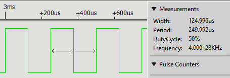
The result is as you would expect:
It is usually simpler to put the configuration details into a function which sets all of the defaults. It is possible to change most of the configuration later. For example: void PWMconfigLow(int gpio, int chan,
This function lets you set the timer, channel, frequency, and resolution in the usual way. The only innovation is to allow the duty cycle to be set as a fraction. So for a 50% duty cycle, you would specify 0.5. |
||||||
| Last Updated ( Wednesday, 05 February 2025 ) |