| Programming The ESP32 In C - PWM First Example |
| Written by Harry Fairhead | ||||||||||||||||||
| Wednesday, 05 February 2025 | ||||||||||||||||||
Page 2 of 5
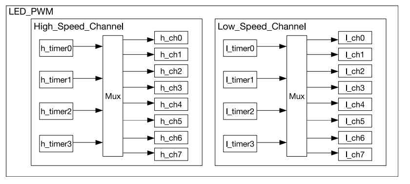
ESP32 PWMThe ESP32 has two PWM hardware implementations. One is intended for use in motor control and has extra features such as a dead zone and auto-braking. The second, LEDC, is specifically designed to drive LEDs with facilities such as auto-dimming plus more exotic features. A PWM generator can be assigned to any GPIO pin. The number of PWM generators an ESP32 has depends on its exact model. They come in two groups – fast and slow. The fast type has the auto-dimming features and is able to smoothly change frequency and duty cycle. The slow type lacks these features and it is up to software to change its frequency and duty cycle. Each group also has a set number of timers which determine how many different frequencies can be generated and a given number of channels.
Notice that a single timer can be shared by more than one channel and any timer can be assigned to any channel. The difference between the high-speed and low-speed channels isn’t as important as you might think. Both can work with an 80MHz clock, but the low-speed channels can also work with an 8MHz clock:
Another difference is that the high-speed channels will change the timer at the end of a count, so generating a glitch-free signal whereas a low-speed channel will change as soon as software instructs it to.
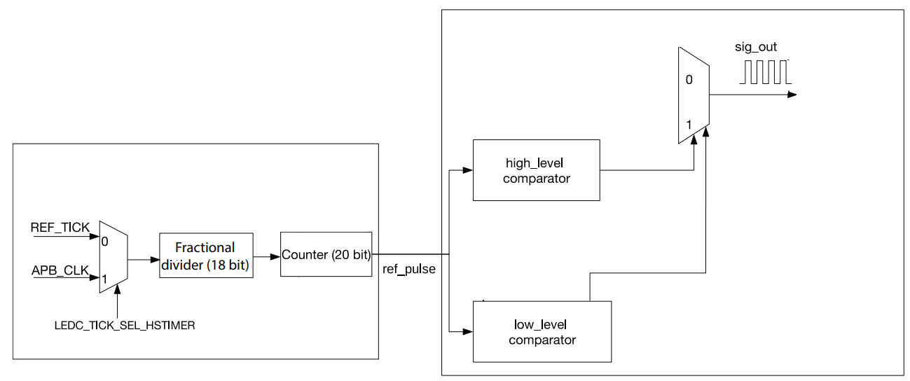
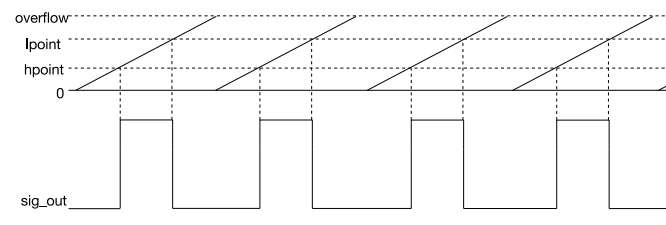
The frequency of the PWM signal is set by the rollover, which depends on the number of bits used in the counter, i.e. between 1 and 20, and the clock frequency. The number of bits used in the counter is related to the resolution with which the duty cycle can be set. For example, if the counter was set to 2 bits the count would be 00, 01, 10 and 11 with rollover at 11. Clearly now you can only set the comparators to the four values which means in theory you could produce a 0%, 50%, 75% or 100% duty cycle.
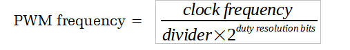
For example, if the clock frequency is 80MHz and the divider is set to 2 the input pulses to the controller are 40MHz. If the duty resolution is set to 8 bits then 28 is 256 and hence the PWM frequency is 156.25kHz and the duty cycle can be set to any of 256 different ratios. Notice that there is more than one way to obtain a given PWM frequency corresponding to different clock frequencies and duty resolutions. In general, you want to select the clock frequency that gives the highest duty resolution. There is a helper function: duty_res = ledc_find_suitable_duty_resolution(
src_clk_freq, timer_freq)
which will find the maximum duty cycle resolution for any given clock and PWM frequency. |
||||||||||||||||||
| Last Updated ( Wednesday, 05 February 2025 ) |