| Programming The ESP32 In C - PWM First Example |
| Written by Harry Fairhead | ||||||
| Wednesday, 05 February 2025 | ||||||
Page 3 of 5
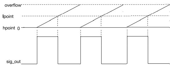
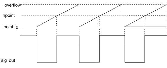
Duty Cycle and PhaseThe software lets you set the duty cycle resolution in terms of the number of bits, the duty cycle as a count and hpoint as a count. This makes it slightly difficult to see what is going on and in particular why you might want to set hpoint at all. Suppose you select duty_res to be 8 bits, that makes the timer roll over at 28-1= 255 and if you set the hpoint to 0 then the output goes high as soon as the timer starts counting. If you set the duty cycle to 127, then lpoint, computed as hpoint+duty cycle is 127. The result is the output goes high at count=0, goes low at count=127 and goes high at the rollover after 255. This is an output with a 50% duty cycle. Now consider what happens if you set hpoint to 127. Now when the count starts the output stays low until the count reaches 127. The lpoint, again computed as hpoint+duty cycle is now 127+127, i.e. 254, which means the output goes low right at the end of the count, just before the rollover.
You can see that moving the hpoint has not affected the duty cycle, but has changed where the pulse starts going high. That is, hpoint sets the phase. If you set hpoint too close to the overflow, the lpoint that completes the pulse will be in the next clock cycle. That is, the position of lpoint is given by: lpoint = (duty cycle + hpoint) mod overflow count
This means you can change the phase from zero to 360 degrees. Notice that PWM channels always start from a low state and this means if hpoint isn’t 0 the very first low may be longer than the following pulses. You can see an example of this later. Setting up the PWMSetting up a PWM source has two steps, configuring a timer and then configuring a channel. For the former you can use: ledc_timer_config(ptimer_conf)
where ptimer_config is a pointer to a struct, timer_config, with the following fields:
				LEDC_HIGH_SPEED_MODE
				LEDC_LOW_SPEED_MODE
		 		LEDC_SPEED_MODE_MAX
LEDC_REF_TICK (1MHz) LEDC_APB_CLK (80MHz) LEDC_SCLK (8MHz) LEDC_AUTO_CLK auto select
Once you have a timer setup the next step is to configure a channel using: ledc_channel_config(pchan_conf)
where pchan_conf is a pointer to a struct with the following fields:
			LEDC_HIGH_SPEED_MODE
			LEDC_LOW_SPEED_MODE
|
||||||
| Last Updated ( Wednesday, 05 February 2025 ) |