| Programming The ESP32 Using Arduino - PWM |
| Written by Harry Fairhead | ||||
| Tuesday, 21 January 2025 | ||||
Page 3 of 3
Uses of PWM – Digital to AnalogWhat sorts of things do you use PWM for? There are lots of very clever uses for PWM. However, there are two applications which account for most PWM applications - voltage or power modulation and signaling to servos. The amount of power delivered to a device by a pulse train is proportional to the duty cycle. A pulse train that has a 50% duty cycle is delivering current to the load only 50% of the time and this is irrespective of the pulse repetition rate. So the duty cycle controls the power, but the period still matters in many situations because you want to avoid any flashing or other effects. A higher frequency smooths out the power flow at any duty cycle. If you add a low-pass filter to the output of a PWM signal then what you get is a voltage that is proportional to the duty cycle. This can be looked at in many different ways, but again it is the result of the amount of power delivered by a PWM signal. You can also think of it as using the filter to remove the high-frequency components of the signal, leaving only the slower components due to the modulation of the duty cycle. How fast you can work depends on the duty cycle resolution. If you work with 8-bit resolution your D-to-A conversion will have 256 steps, which at 3.3V gives a potential resolution of 3.3/256 or about 13mV. This is often good enough. The PWM output in this configuration mimics the workings of a, very slow, 8-bit D‑to‑A converter. To demonstrate the sort of approach that you can take to D-to-A conversion, the following program creates a sine wave. To do this we need to compute the duty cycle for 256 points in a complete cycle. We could do this each time a value is needed, but to make the program fast enough we have to compute the entire 256 points and store them in an array. Notice that the ESP32-S2 doesn’t have floating-point arithmetic implemented in hardware, but the original ESP32 and the ESP32-S3 do support hardware floating point although it isn’t very fast. The program is: uint8_t wave[256];
void setup() {
for (int i = 0; i < 256; i++) {
wave[i] = (uint8_t)((128.0 + sinf((float)i * 2.0 *
3.14159 / 255.0) * 128.0));
}
}
void loop() {
for (int i = 0; i < 256; i++) {
analogWrite(2, wave[i]);
delayMicroseconds(1000);
}
}
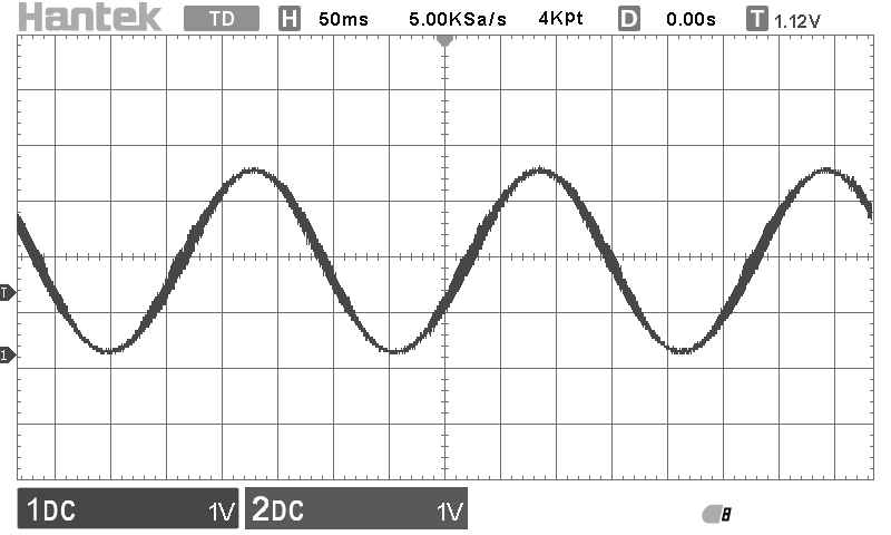
The 8-bit duty cycle values needed are computed and stored in the wave array. A for loop is used to set the duty cycle from the array. To make it work we need to perform an update roughly every timer overflow and this is done automatically using the delayMicroseconds. The waveform repeats after around 250ms, which makes the frequency around 4Hz. To see the analog waveform, we need to put the digital output into a low-pass filter. A simple resistor and capacitor work reasonably well:
With R1 at 7.5kΩ and C1 at 0.22µF the filter's cutoff is around 100Hz and might be a little on the high side for this low-frequency, 4Hz, output, but it produces a reasonable waveform:
You can use this technique to create a sine wave, or any other waveform you need, but for high-quality audio you need a higher sampling rate. This is also the highest frequency 256 level sine wave that you can produce by this method. To do better we need to increase the PWM frequency so that it can be updated faster. In Chapter but not in this extract
Summary
Programming The ESP32 In C
|
||||
| Last Updated ( Tuesday, 21 January 2025 ) |


