| Programming The ESP32 Using Arduino - PWM |
| Written by Harry Fairhead | ||||
| Tuesday, 21 January 2025 | ||||
Page 2 of 3
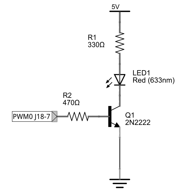
Arduino Simple DACThe Arduino library provides a very simple way to generate a PWM signal. The only problem is that the frequency is fixed and all you can alter is the duty cycle: analogWrite(pin, value) where pin is the GPIO line to use and value is the duty cycle specified as a number between 0 and 255 corresponding to 0% and 100%. Obviously to set a duty cycle of d all you have to do is set value to 255*d/100. For example, for a 50% duty cycle you would set value to 255*50/100=127.5 which is 127 or 128 depending on rounding. The fixed frequency used depends on the processor, but for the ESP32 it is 1kHz. This is a high enough frequency not to be noticeable when driving an LED or a motor, but for other loads you might need a filter to smooth out the signal. Controlling an LEDYou can also use PWM to generate physical quantities such as the brightness of an LED or the rotation rate of a DC motor. The only differences required by these applications are to do with the voltage and current you need and the way the duty cycle relates to whatever the physical effect is. In other words, if you want to change some effect by 50%, how much do you need to change the duty cycle? For example, how do we "dim” an LED? The simplest example is to drive the LED using a PWM signal: void setup() {
}
void loop() {
for (int d = 0; d < 256; d++) {
analogWrite(2, d);
delay(10);
}
}
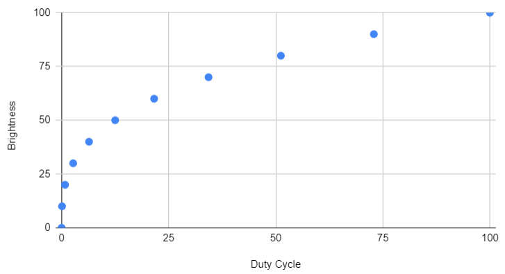
If you try this out you will see the LED slowly increase in brightness, but it seems to be a longer time at maximum brightness than at any other value. This is a consequence of the non-linear relationship between duty cycle and perceived brightness. By changing the duty cycle of the PWM pulse train you can set the amount of power delivered to an LED, or any other device, and hence change its brightness. If you use a 50% duty cycle, the LED is on 50% of the time and this makes it look as if it is half as bright. However, this is not the end of the story as humans don’t respond to physical brightness in a linear way. The Weber-Fechner law gives the general relationship between perceived intensity and physical stimulus as logarithmic. In the case of an LED, the connection between duty cycle and brightness is a complicated matter, but the simplest approach uses the fact that the perceived brightness is roughly proportional to the cube root of the physical brightness. The exact equations, published as CIE 1931, are: L= 903.3 ∙ (Y / Yn) (Y/ Yn) ≤ 0.008856 L= 116 ∙ (Y / Yn)1/3 – 16 (Y/ Yn) > 0.008856 where L is the perceived brightness and Y / Yn is a measure of physical brightness. While the exact relationship is complicated, in most cases a roughly cubic law, obtained by inverting the CIE relationship, can be used: d=kb3
The graph above shows the general characteristic of the relationship for a duty cycle of 0 to 100% on the y-axis and arbitrary, 0 to 100, perceived brightness units on the x-axis. As the LED, when powered by a PWM signal, is either full on or full off, there is no effect in the change in LED light output with current - the LED is always run at the same current. What all of this means is that if you want an LED to fade in a linear fashion you need to change the duty cycle in a non-linear fashion. Intuitively, it means that changes when the duty cycle is small produce bigger changes in brightness than when the duty cycle is large. A program to implement cubic dimming can be created by simply changing one line in the previous program: void setup() {
}
void loop() {
for (int d = 0; d < 256; d++) {
analogWrite(2, d * d * d / 255 / 255);
delay(10);
}
}
If you try this out you should notice that the LED changes brightness more evenly across its range. In most cases it is irrelevant exactly how linear the response of the LED is, a rough approximation looks as smooth to the human eye. You can even get away with using a square law to dim the LED. The only exception is when you are trying to drive LEDs to create a gray-level or color display when color calibration is another level of accuracy. There is also the question of what frequency we should use. Clearly it has to be fast enough not to be seen as flickering and this generally means it has to be greater than 80Hz, the upper limit for human flicker fusion, but, because of the strobe effect, flickering becomes more visible with moving objects. The faster the LED switches on and off, the less flicker should be visible, but before you select frequencies in the high kHz range it is worth knowing that an LED has a minimum time to turn on and so frequencies at low kHz work best.
|
||||
| Last Updated ( Tuesday, 21 January 2025 ) |

