| Exploring Edison - Life At 1.8V |
| Written by Harry Fairhead | ||||
| Monday, 04 January 2016 | ||||
Page 3 of 3
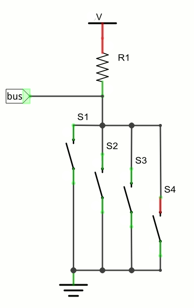
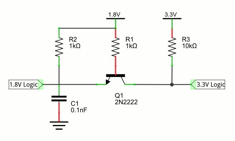
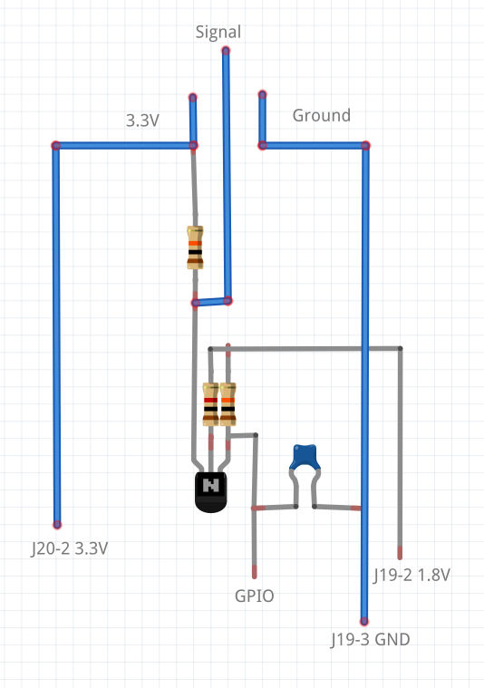
Bi-directional BusThe biggest problem in converting from 1.8V to 3.3 or 5V is when you need to work with a bi-directional bus. There are, roughly speaking, three types of bi-directional bus - wire or, wire and and tristate. The most commonly encountered is a wire or or open collector bus. This is used for I2C and many other one wire serial buses. The key idea is that the bus line is connected to a voltage reference via a resistor, generally a pull up resistor. This allows any device connected to the bus to ground it and so pull the bus line down. If more than one device pulls the bus down then no harm is done. However the bus line only pulls up when all of the connected devices In the diagram above each of the switches represents a device connected to the bus. In practice the switches would be an active device such as a BJT or an FET but the principle is the same. You can see that closing any one of the switches grounds the pull up resistor which places the bus in low state. If you need to connect a 3.3V or 5V open collector bus to a 1.8V Edison input then you can make use of an chip designed to do the job but in many cases a simple classic single transistor level shifter can do the job. For conversion to 3.3V you will often see an FET used but for the low voltage involved in a 1.8V conversion a BJT does the job very well. This assumes that the output line is in pull up or open collector mode. The default for the mini-breakout board is pull up using a 50K resistor. The circuits described work in this mode. For example:
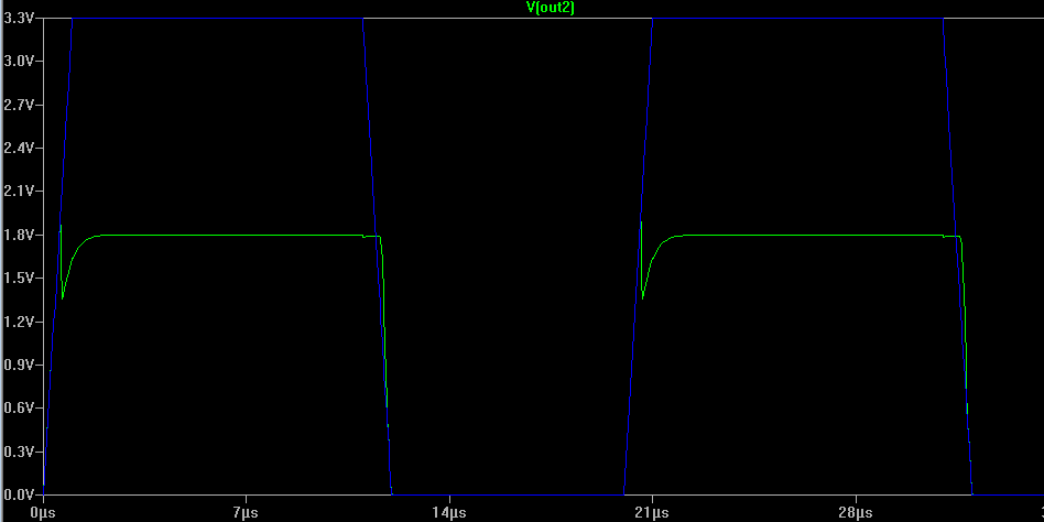
In practice R2 can be anywhere from 1K to 5K and R3 anywhere from 5K to 10K depending on what is being driven. Notice that this assumes that the GPIO pin is in open collector mode with an external pull up resistor. To understand how this works we have to consider what happens when each side of the bus is pulled low. If the 1.8V logic input is pulled low then the emitter of the transistor is grounded and as the base is at 1.8V the transistor switches on and saturates so pulling the 3.3 logic bus down. The more difficult situation is when the 3.3V logic linput is pulled low. In this case the collector is grounded and the base being at 1.8V [its tje tranistor into reverse active mode i.e. with collector and emittor swapping roles. In this mode the transistor is still a current amplifier but with a much reduced gain (hfe). Given sufficent drive current however the transistor will still saturate and hence pull the 1.8V logic side of the bus low. The reason for the capacitor is that as the transistor changes operational mode there is a charge storage effect which causes the voltage to suddenly drop. An effect you can see clearly:
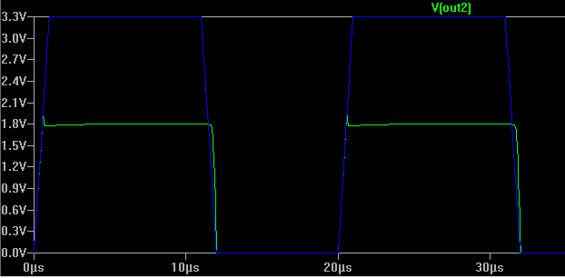
The blue trace is the 3.3V input signal and the green trace is the 1.8V output. In practice the undershoot can cause the Edison to detect two pulses in place of one. With a small capacitance in place the effect is reduced:
Notice that as in the case of the single transistor non-inverting buffer the big problem is that there is no current amplification. When the Edision pulls the bus low it has to sink the current through R1, R2 and R3. and the same is true on the 3.3V side. In this case the total current is less than 1.5mA. The circuit works just as well at 5V with a slighly higher current. You might expect the Edison's side of the bus needs to be driven with an open collector i.e. with its own pull up which is the default mode. In fact it doesn't make any difference as the Edison is the only device driving the 1.8V logic input. You can use an active high/active low drive as long as the Edison is the only device driving the bus and then the line is changed to an input to read the response from the responding device. If the output line drives the bus both high and low then a problem only arrises when the slave attempts to drive the bus in the opposite direction. In most cases the slave doesn't attempt to drive the bus at the same time as the master and so the type of drive is irrelevant as long as the line reverts to input as soon as a slave starts transmitting data. However it takes time to convert an output line to an input and this is sometimes an additional problem. Converting other types of bus are more difficult but follow the same general idea. You can build the circuit using a prototyping board or you can built it in-situ on the device you need to convert. Something like: where the device in question is connected to the three wires at the top of the diagram. This is used in the next two chapters to interface bidirectional pull up buses.
Now On Sale!You can now buy a print edition of Exploring Intel Edison.You can buy it from:
USA and World Amazon.com Chapter List
<ASIN:1871962447> To be informed about new articles on I Programmer, sign up for our weekly newsletter, subscribe to the RSS feed and follow us on, Twitter, Facebook, Google+ or Linkedin.
Comments
or email your comment to: comments@i-programmer.info <ASIN:B00ND1KH42@COM>; <ASIN:B00ND1KNXM> <ASIN:B00ND1KH10>
|
||||
| Last Updated ( Wednesday, 11 May 2016 ) |