| Getting Started With Digital Logic - Logic Gates |
| Written by Harry Fairhead | ||||||||||||||||||||
| Saturday, 11 January 2025 | ||||||||||||||||||||
Page 2 of 4
SmartSim- simulation softwareThere are a number of simulation packages available for download but they all have one problem or another. One of the best, however, is SmartSim which has been adopted as prefered software for the Raspberry Pi. It comes ready installed on the Pi but the website has instructions how to install it if you are using an old version of Raspian. If you have Windows, Mac OS or Linux then you can download it as a zip. You simply unzip the package to a suitable folder, and you run smartsim.exe. You can download it from: Once installed, using SmartSim is fairly obvious but there are some principles of using the UI that will help get you started.
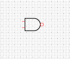
Many of these ideas will become clear as we build a circuit. A first circultStart SmartSim, select the AND tool and click to create a gate on the design surface.Select the Invert tool and click on the output pin - you now have a NAND gate:
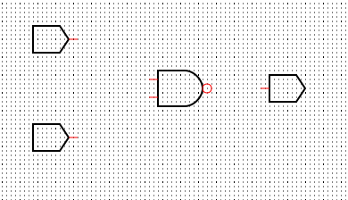
Next select the Toogle tool and place two toogle components near the inputs and select the Reader tool and place a reader near the output.
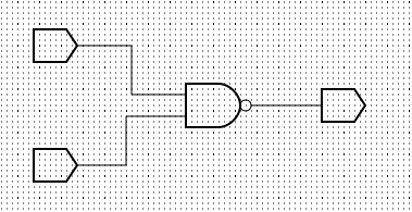
Next wire up the switches to the NAND gate inputs to the toogles and the output to the reader. Click on the starting point of each wire and click twice on the end point - you don't have to make neat bends in the wires. To delete a wire select the delete tool and click on the wire.
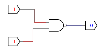
Now use the Component, Set as Root command and then Run Now if you click on the toggle you will notice that they turn from a blue zero to a red 1 and back again when you click again. The Reader component shows you the state of the output of the gate - blue zero or read one. If you play with this circuit you will see that you only get a blue zero when both inputs are red ones.
This corresponds with the NAND truth table which is:
where, of course, T is True or ON and F is False or OFF. |
||||||||||||||||||||
| Last Updated ( Saturday, 11 January 2025 ) |