| Getting Started With Digital Logic - Logic Gates |
| Written by Harry Fairhead | |||||||||||||||||||||||||||||||||||||||||
| Saturday, 11 January 2025 | |||||||||||||||||||||||||||||||||||||||||
Page 1 of 4 How to get hands-on with logic gates without soldering. Using the SmartSim simulator, the hardware becomes software and you can avoid burnt fingers and burned components. So let's get started. Getting Started With Digital Logic
Logic is an essential piece of knowledge for any programmer or computer scientist. However, many people learn the theory but never discover the practice. It is easy and rewarding to discover how what you know about logic can be built into hardware. You not only learn how to create real physical computing devices, but you get to understand computers so much better. Of course, the downside is all that soldering and burned components - but using a simulator the hardware becomes software. So let's get started. Logic is the key to implementing any sort of computing device no matter what technology it is based on. In this article we will take a look at how simple logic gates can be used to implement Boolean logic and how they can be realized as hardware. The first stage, however, is to use a simulator to see what it is all about. What is logic?Logic is about how we combine the values true and false to produce another value, that is also true or false. You can also use one and zero in place of true or false. There are three basic logical operations - AND, OR and NOT - from which all others can be derived. The rules for combining expressions are usually written down as tables listing all of the possible outcomes. These are called truth tables and for the three fundamental operators they are:
In software, logic commonly occurs as part of an If statement or other conditional. For example:
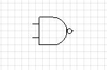
only executes the instructions in the curly brackets if both x and y are greater than 0. Moving from this idea to hardware-based logic can seem difficult, and in many ways it is easier to keep the truth tables in mind when you first meet hardware logic. Hardware gates - the 74 familyBoolean gates were the first computational elements to be fabricated as integrated circuits. A hardware gate works, not with true and false, but with two voltage levels. Usually high is taken as true or the "1" state and low is usually taken as false or the "0" state. Of course, it matters what voltages are used and logic gates are usually made to be part of a family of gates that work at a specified pair of voltages. One of the first logic families was the 7400 or 74 family introduced by Texas Instruments. You could say that it was the 74 family that started the mass use of integrated circuits. You will also hear the 74 family referred to as TTL - or Transistor Transistor Logic - because of the technology that is used to implement the gates, but this doesn't really matter. What really matters is the voltage that the gates work at. The original 74 family used 5V as the true/one level and 0V as the false/zero level. If you want the whole story then there is a range of voltages around 5V that a gate will treat as a high input and a range around 0V that the gate will treat as a low but for the moment you can get a long way just thinking that 5V is high and 0V is low. It is also worth pointing out that gates are electronic circuits and they need power to operate. The 74 family has to be powered by a 5V source and this fits in nicely with the logic inputs needed. As things have developed since the original 74 family was introduced, logic has tended to work with a lower range of voltages to conserve power and there are other technologies as well as TTL, CMOS for example, which have other advantages, but for the moment we will work with the venerable 74 family. The 7400At the head of the 74 family is the 7400 Quad Nand gate, which is where the family started and where it gets its name from. A NAND gate is an AND gate followed by a NOT gate. Each gate in the 7400 has two inputs and one output and it implements the logic NOT(A AND B) where A and B are the two inputs. A NAND gate is a wonderful thing because using just it you can implement any logic circuit you care to invent. It is an example of a universal gate - there are others. The symbol for a two input NAND gate is:
The two inputs are on the left and the output is on the right. It is also worth knowing that the small circle means NOT so this is an AND gate followed by a NOT i.e. a NAND gate. |
|||||||||||||||||||||||||||||||||||||||||
| Last Updated ( Saturday, 11 January 2025 ) |