| The Pico/W In C: Direct To Hardware |
| Written by Harry Fairhead | |||||||||||||||||||||
| Tuesday, 21 February 2023 | |||||||||||||||||||||
Page 3 of 4
Example I - EventsThe SDK does a fairly good job of covering all of the possible ways you might want to access the hardware but there are some omissions. In Chapter 7 the idea of events was introduced, but the SDK doesn’t provide any access to events. The solution is to add our own function that accesses the GPIO register that records interrupts. This is a register in the GPIO set of registers rather than the SIO as GPIO interrupts aren’t specific to what is controlling the GPIO line.
Now that we know about using structs to gain access to registers it makes sense to use the struct that the SDK defines to access the GPIO registers: typedef struct {
struct {
io_rw_32 status;
io_rw_32 ctrl;
} io[30];
io_rw_32 intr[4];
io_irq_ctrl_hw_t proc0_irq_ctrl;
io_irq_ctrl_hw_t proc1_irq_ctrl;
io_irq_ctrl_hw_t dormant_wake_irq_ctrl;
} iobank0_hw_t;
The struct is set to start at the base of the GPIO registers and you can see that it starts off with the status and control registers for each GPIO line and then the four raw interrupt registers. The format of the raw interrupt registers is more complicated than the previous “one bit to one GPIO line” arrangement we have encountered before. In this case there are four bits per GPIO line and they record different interrupt types. The first four bits of the first register record interrupts on GP0:
This pattern is repeated for each of the GPIO lines and, when all of the bits in the first register have been used, the pattern continues in the second register with GP8 and so on. Each register records the event data for eight GPIO lines. Notice that each of the bits is set if the event that would cause the interrupt occurs – the interrupt itself only occurs if it is enabled. What this means is that the level bits track the current level of the GPIO line and the edge bits are set if an edge of that type has occurred. The WC in the third column indicates that the bit is cleared if you write to it and this is how the event is cleared, of course RO means Read Only. We now know how to check for an event. All we have to do is read the value of the four bits corresponding to the GPIO line. If we are interested in GPIO line gpio then it is easy to see that the register that has its information is gpio/8. A mask for the correct four bits within the register is more difficult to devise, but you have to shift 0xFF, i.e. 1111, left by 4*(gpio%8). To see that this works try it out with a few values. Using this we can now get the four bits: iobank0_hw->intr[gpio/8] & mask However, this gives the bits in their original position within the word. To get a right-aligned four bits we need to shift them down by 4*(gpio%8). Putting all this together gives the function introduced in Chapter 7: uint32_t gpio_get_events(uint gpio)
{
int32_t mask = 0xF << 4 * (gpio%8);
return (iobank0_hw->intr[gpio / 8]
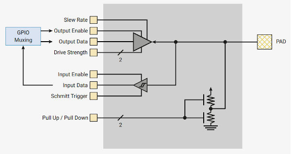
To clear the raw interrupt bit you simply have to write a zero to it and there is already an SDK function that will do this. Example II PAD - Pull, Drive and SchmittEach GPIO line has an identical input-output stage, called a PAD, which is the connection to the outside world no matter what mode the GPIO line is being used in. This is fundamental to the workings of the GPIO line and you might be wondering why it is being introduced so late? The answer is that the SDK doesn’t fully support it and the aspects of the PAD that it does support, Pull Up and Pull Down, are simple enough. If you are interested in the finer details then you are going to have to implement functions that work with them. The structure of the PAD can be seen below:
You can see that under program control you can set the Pull Up/Pull Down configuration and enable the input/output. The input also has a Schmitt trigger that can be enabled to clean up noisy inputs. The output can be customized by slew rate, how fast it changes and drive strength. Before moving on to the software, it is worth explaining the basic ideas of the options. The Schmitt trigger adds hysteresis to the input line. This means that before the state changes from high to low it has to cross a threshold, but to change back to a low state it has to cross a lower threshold. This acts like a limited debounce mechanism in that it stops the line from going low because the input drops a little after going high. The Pico’s Schmitt trigger uses thresholds of 0.2V difference if the processor supply voltage is 2.5V to 3.3V and 0.18V if the voltage is 1.8V. What this means is that at 3.3V the input has to be greater than 2V to be a one, but after this the voltage has to fall to 1.8V before it changes back to a zero. For a zero the thresholds are 0.8V to change a zero and 2V to change back to a one. The output drive strength isn’t to do with how much current the GPIO line can source, it is about the voltage output at different currents. It is the effective output resistance. Each time the drive current is increased by 2mA another transistor is used in the drive, so lowering the output resistance. This has the effect of increasing or decreasing the voltage at the pin. For example, if you set the drive to 1 then if you want to keep the output voltage at or above 2.62V, i.e. a logic 1, then you can’t draw more than 2mA. Put more simply, if you want the output to maintain voltages that are within the threshold for a logic 1 or 0 then you can only draw 2, 4, 8 or 12mA from the GPIO line depending on the setting of the drive strength. If you draw more current then this is fine, but the voltage will fall below the standards for 3.3V logic. |
|||||||||||||||||||||
| Last Updated ( Tuesday, 21 February 2023 ) |