| The Pico/W In C: Direct To Hardware |
| Written by Harry Fairhead | |||||||||||||||||||||||||||||||||||||||||
| Tuesday, 21 February 2023 | |||||||||||||||||||||||||||||||||||||||||
Page 2 of 4
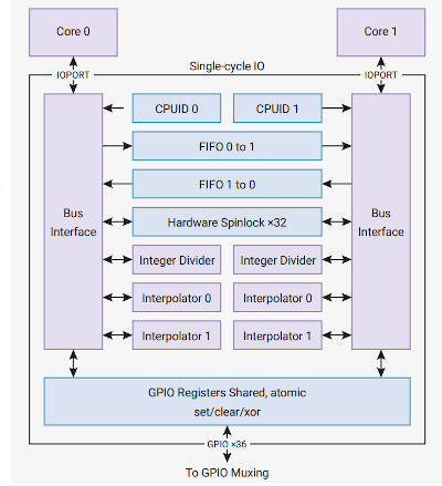
At this point you might think that we are ready to access the state of the GPIO lines for general input and output. This isn’t quite the whole story. To accommodate the fact that the processor has two cores, and to make access faster to important devices, there is a special connection, the SIO or Single-cycle IO Block, between the cores and, among other things, the GPIO. The SIO connects directly to the two cores and they can perform single-cycle 32-bit reads and writes to any register in the SIO. Notice that the SIO is not connected via the general address bus.
Notice that the GPIO lines are multipurpose and to use a GPIO line via the SIO you have to set its mode to SIO either via direct access to its control register or using the SDK function: gpio_set_function(pin,GPIO_FUNC_SIO); In this sense the SIO is just another peripheral that can take control of a GPIO line. The SDK gpio_init function automatically sets the GPIO line to use the SIO, so you are using the SIO even if you don’t realize it. The SIO provides a set of registers that makes using the GPIO much faster and much easier. The basic registers are:
There are also three registers – SET, CLR and XOR - that make working with GPIO_OUT and GPIO_OE easier. Each of these can be thought of as a mask that sets, clears or XORs bits in the corresponding register. For example, GPIO_OUT_SET can be used to set just those bits in GPIO_OUT that correspond to the positions that are set high. The locations of these registers are as offsets from 0xd0000000 (defined as SIO_BASE in the SDK):
Now we can re-write Blinky, but this time using direct access to the SIO GPIO registers. This only works on the Pico and not the Pico W because it doesn’t use GP25 to control the LED. If you want to try this on a Pico W change the GPIO number to something other than 25 and use an external LED: #include "pico/stdlib.h"
#include "hardware/gpio.h"
int main()
{
gpio_init(25);
This program uses the SDK to set the GPIO line to SIO control and output. If you think that this is cheating, it is an exercise to set the line correctly using the GPIO control register and the SIO. The only possible confusion is the use of the offset divided by 4. The reason for this is that the pointer to the start of the registers is declared as uint32_t and, by the rules of pointer arithmetic, adding one to it adds the size of a uint32_t, i.e. 4. To keep the address as a byte address we have to divide the offset by 4 and rely on the pointer arithmetic to multiply it by 4 before use. The SDK Set FunctionThe single instruction in our previous program: *(SIO + 0x018 / 4) = 1ul << 25; is equivalent to the SDK’s gpio_set function. Now that we know how things work, it is worth looking at the way the SDK does the job: static inline void gpio_put(uint gpio, bool value) {
This doesn’t really tell us much about how things work because the put function simply passes the job onto the set or clr function. You can at least see that the function creates a bit mask in the same way our function did. Let’s look at set and see how it completes the job: static inline void gpio_set_mask(uint32_t mask) {
sio_hw->gpio_set = mask;
}
The key to understanding this is that sio_hw is a struct that has fields for each of the SIO registers and its starting address is set to the start of the SIO. This is a fairly standard way of getting easy access to registers specified as offsets from a base address without having to do pointer arithmetic or defining lots of constants. If you take a look at the start of the sio_hw definition, it should make sense: typedef struct {
To set this struct so that its fields correspond to the registers we simply set its starting location to the address of SIO_BASE: #define sio_hw ((sio_hw_t *)SIO_BASE) Following this, when you set and retrieve values from the struct’s fields you are working with the registers. |
|||||||||||||||||||||||||||||||||||||||||
| Last Updated ( Tuesday, 21 February 2023 ) |