| Raspberry Pi IoT In C - 1‑Wire Bus Basics |
| Written by Harry Fairhead | |||
| Monday, 03 October 2022 | |||
Page 1 of 2 The 1-Wire bus is a favourite find out how it works. This is an extract from Raspberry Pi IoT in C, Second Edition. Raspberry Pi And The IoT In C Second EditionBy Harry Fairhead
Buy from Amazon. Contents
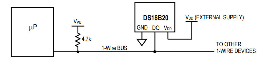
The Raspberry Pi is fast enough to be used to directly interface to a 1‑wire bus without the need for drivers. The advantages of programming our own 1‑wire bus protocol is that it doesn't depend on the uncertainties of a Linux driver. The 1‑wire bus is a proprietary bus that is very easy to use and has a lot of useful devices you can connect to it, including the iButton security devices. However, probably the most popular of all 1‑wire devices is the DS18B20 temperature sensor - it is small, very cheap and very easy to use. The next two chapters show you how to use both of these, but first let's deal with the general techniques needed to work with the 1‑wire bus. There are 1‑wire drivers for Linux and these are most commonly used in Python and other higher level languages that work with the bus. To make use of them you have to install the drivers and occasionally there are compatibility problems. If you are programming in C then you have more than enough speed to write your own 1‑wire protocol functions and this has the advantage of not requiring any interaction with Linux to work. You are also free to modify and extend the 1‑wire functions without having to become involved in writing Linux modules. If you are interested in using the Linux drivers then see: Raspberry Pi IOT in C With Linux Drivers, ISBN: 9781871962642. The HardwareOne-wire devices are very simple and only use a single wire to transmit data:
The 1‑wire device can pull the bus low using its Tx line and can read the line using its Rx line. The reason for the pull-up resistor is that both the bus master and the slave can pull the bus low and it will stay low until they both release the bus. The device can even be powered from the bus line by drawing sufficient current through the pull-up resistor - so called parasitic mode. Low power devices work well in parasitic mode, but some devices have such a heavy current draw that the master has to provide a way to connect them to the power line - so called strong pull-up. In practice parasitic mode can be difficult to make work reliably for high power devices. In normal powered mode there are just three connections - V power, usually 3.3V for the Pi; Ground and Data:
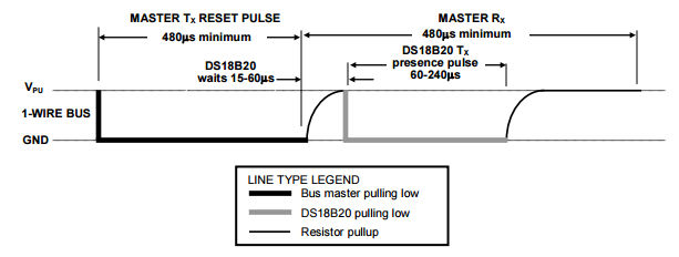
For simplicity, it is better to start off with a single device and avoid the problem of enumerating the devices on the bus, although once you know how everything works this isn't difficult to implement. To get started select a 1‑wire device that you want to work with and set it up ready to talk to the Pi of your choice. In the next chapter we show how to work with an iButton and in the following one the DS18B20 is explained. The functions described in this chapter should work with any 1‑wire device. It is worth mentioning that there is a Linux driver for the 1‑wire bus that makes it look like working with a file in sysfs. How to do this is covered in Raspberry Pi IOT in C With Linux Drivers, ISBN: 9781871962642. In this book we concentrate on using 1‑wire directly as this allows you to customize to any device and it isn’t subject to change. InitializationEvery transaction with a 1‑wire device starts with an initialization handshake. First we have to work out how to configure the GPIO line. This example assumes that the 1‑wire device is connected to pin 7. If this isn't the case, change the pin enumeration to the correct pin. For full practical examples, see the next two chapters. In this chapter we use GPIO lines to interface with the 1-wire bus but in Chapter 16 the UART connection is used to create an alternative method with some advantages. You might think that we have to initialize the GPIO line so that it works in pull-up mode. This isn't necessary and the default push-pull mode will do. The reason is that, in the case of the 1‑wire bus, the master controls when other devices send their data. Typically the master sends a pulse and then the slaves respond by pulling the line low. As long as the master doesn't drive the line during the period when the slaves are responding, everything is fine. What we do in practice is to configure the GPIO line for output only when the master needs to drive the line. Once the master is finished the GPIO line is set back to input and the pull-up resistor is allowed to pull the line back up. After this, any slave wanting to send data is free to pull the line low. The first transaction we need is the initialization pulse. This is simply a low pulse that lasts at least 480µs, a pause of 15µs to 60µs follows and then any and all of the devices on the bus pull the line low for 60µs to 240µs.
This is fairly easy to implement as a function: int presence(uint8_t pin) {
bcm2835_gpio_fsel(pin, BCM2835_GPIO_FSEL_OUTP);
bcm2835_gpio_write(pin, LOW);
bcm2835_delayMicroseconds(480);
bcm2835_gpio_fsel(pin, BCM2835_GPIO_FSEL_INPT);
bcm2835_delayMicroseconds(70);
uint8_t b = bcm2835_gpio_lev(pin);
bcm2835_delayMicroseconds(410);
return b;
}
We pull the line low for 480µs and then let it be pulled back up by changing the line to input, i.e. high impedance. After a 70µs wait, which is right at the start of the guaranteed period when the line should be low if there is an active device on the bus, we read the input line and then wait another 410µs to complete the data slot. The timings in this case are not critical as long as the line is read while it is held low by the slaves, which is never less than 60µs and is typically as much as 100µs. The actual pulse timings with the values given are a 482µs reset and a total slot time of 632µs. If there is a device the function should return a 0 and if there are no devices it should return a 1. #include <bcm2835.h>
#include <stdio.h>
int presence(uint8_t pin);
int main(int argc, char **argv) {
if (!bcm2835_init())
return 1;
if (presence(RPI_BPLUS_GPIO_J8_07) == 1) {
printf("No device \n");
} else {
printf("Device present \n");
}
bcm2835_close();
return 0;
}
If you try this partial program and have a logic analyzer with a 1‑wire protocol analyzer you will see something like:
Seeing a presence pulse is the simplest and quickest way to be sure that your hardware is working. |
|||
| Last Updated ( Wednesday, 05 October 2022 ) |