|
Page 1 of 3 Input is more varied and challenging than output. In this extract from a new book on using GPIO Zero on the Pi in Python we look at its variety.
Raspberry Pi IoT In Python Using GPIO Zero
Second Edition
By Harry Fairhead & Mike James
Buy from Amazon.
Contents
- Why Pi for IoT?
- Getting Started With Python And GPIO Zero
- Introduction to the GPIO
- Python - Class and Object
- Simple On/Off Devices
Extract 1: On/Off Devices *
- Pins And Pin Factories
Extract 1: Pins
- Some Electronics
- Simple Input
Extract 1:Getting Input ***NEW!!
- Complex Input Devices
Extract 1: Complex Input *
- Pulse Width Modulation
Extract 1: PWM*
- Controlling Motors And Servos
Extract 1: DC Motors *
- Working With Compound Devices
Extract 1: Compound Devices*
- The SPI Bus
- Custom SPI Devices
- Using The Lgpio Library
- Appendix Visual Studio Code Remote Python
*Extracts from first edition - will be updated.
Complex Input Devices
These input devices are not complex in the sense of difficult, they just have more features than a simple button. All of the devices inherit from SmoothedInputDevice and the general idea is that a single input isn’t sufficient to act on. What is required is an average reading so reducing noise.
SmoothedInputDevice
The base class for all of this set of input devices is SmoothedInputDevice.
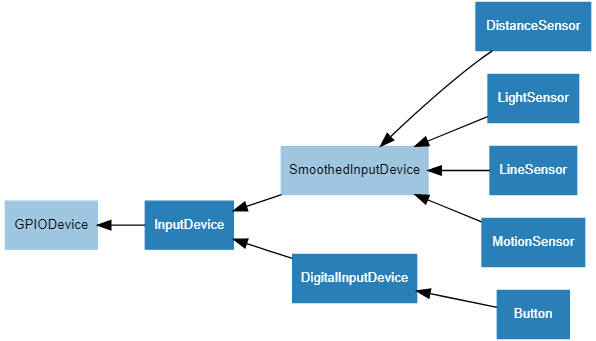
The SmoothedInputDevice has all of the properties of InputDevice and, in addition, it sets up a queue of readings. The actual value of the device is obtained by applying a function, usually an average, to the readings in the queue. A background thread is used to take regular readings and the function is computed when you use a value.
The constructor has a large number of parameters:
SmoothedInputDevice(pin, *, pull_up=False,
    active_state=None,
       threshold=0.5, queue_len=5, sample_wait=0.0,
            partial=False, average=median, ignore=None,
                                       pin_factory=None)
The parameters concerned with setting up the queue are:
-
queue_len The length of the queue, i.e. the number of readings that the function is applied to. The default is 5.
-
threshold The value that is used as a cut-off for the device being activated. If the read value is greater than threshold, the device is active.
-
sample_wait The time between readings in seconds. The default is 0, which means read as fast as possible.
-
partial If True an attempt to read the device returns with a value, even if the queue isn’t full. If False, the default, a read blocks until the queue is full.
-
ignore A set of values that represents non-readings and should be ignored in the calculation of the average. Defaults to None.
-
average The function applied to the values in the queue to get the final value. It defaults to median, which is the middle value in the queue.
Using a SmoothedInputDevice is just a matter of setting up the degree of smoothing needed – i.e. the speed of reading, the number of data points to average, and the function that should be used to average them.
It should be obvious that, whatever the SmoothInputDevice is reading, it can’t be a single GPIO line that returns a 0 or a 1. In most cases averaging this using median would return 0.5. However averaging using average would give you a value that was proportional to the ratio of ones to zeros in the measurement interval. In the same way, you can create a device which returns a number proportional to the time a GPIO line is high.
Using the TRCT5000 Line Sensor
The LineSensor device makes use of a module based on the TRCT5000 infrared emitter and sensor.
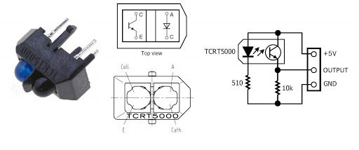
To make this suitable for use with a GPIO line you need to add some electronics:
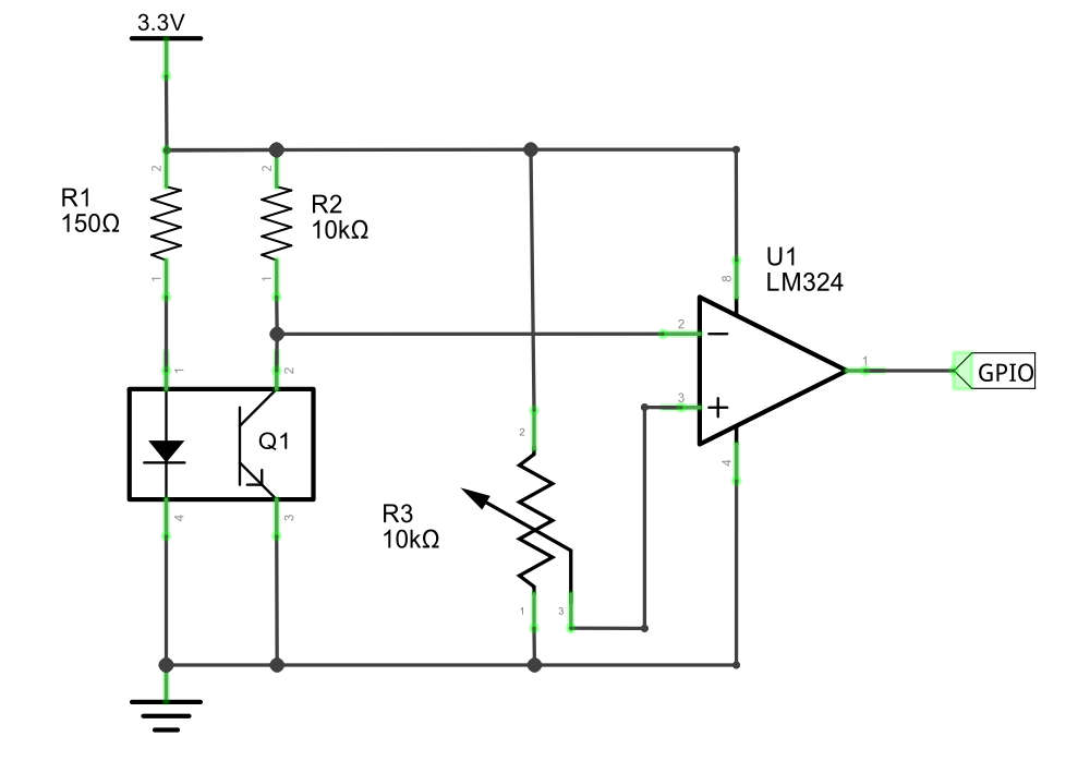
The IR diode sends a beam of IR out of the device and if it is reflected back, the photo transistor switches on. The LM324 U1 outputs a high signal when the voltage from the IR sensor is greater than that set on the potentiometer, R3. That is, R3 acts as a sensitivity control.
You don’t need to build the circuit because you can buy ready-built modules:
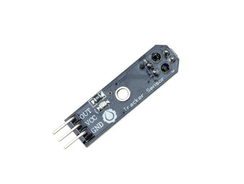
You simply connect the three pins to 3.3V, ground and a GPIO line of your choice. It is worth knowing that some modules output high when over a white line and some go low.
Once you have the hardware connected you can create a LineSensor using the constructor:
LineSensor(pin, *, queue_len=5, sample_rate=100,
          threshold=0.5,
                partial=False, pin_factory=None)
You can read the value property to discover if the sensor is over a reflective surface or not:
from gpiozero import LineSensor
sensor = LineSensor(4)
while True:
    if sensor.value>0.5:
         print('Line detected')
    else:
        print('No line detected')
You can also use the wait_for_line, wait_for_no_line, when_line and when_no_line events.
In practice setting the threshold control on the hardware is likely to be more important than tuning the software.
|