| Adding WiFi To The Pico 2 |
| Written by Harry Fairhead | |||||||||
| Monday, 19 August 2024 | |||||||||
Page 2 of 8
Connecting the ESP8266 ESP-01There a number of minor problems in using the ESP8266. The first is that it comes with an 8-pin male connector which is not prototype board friendly. The best solution to this is to use some female-to-male jumper cables to connect it to the prototype board or use female-to-female cables to connect directly to the Pico. Note that for high baud rates cables should be kept as short as possible. You can power the ESP8266 directly from the Pico's 3.3V supply pin, but if possible it is better to use an alternative as, when transmitting, the ESP8266 takes a lot of current, 300mA or so, and this means there isn't a lot left over to power other things. The maximum current for the Pico’s 3.3V isn’t given, but the chip used claims to be happy at 1200mA and it worked to run all of the examples in this chapter. The pinout of the ESP-01 is usually shown from the component side, but in fact the pins that you want to connect to are on the other side. To make things easier, the two views are given in the diagram: 1 Ground connect to ground
AT CommandsThe key idea in using the ESP8266 is that the Pico has to send an AT command, literally the characters AT, followed by other command strings. The command has to end with \r\n for the ESP8266 to take notice of it. You can find a fill list of commands at the Espressif web site, but the most important are: AT Attention +IPD Data This is just a very general overview and omits the commands that allow the device to work as an access point. It is assumed that client mode is the more common application, but it isn't difficult to extend this example to access point operation. SetupWe need a function to set up the hardware ready to communicate with the device: int initWiFi()
{
uart_init(uart1, 115200);
gpio_set_function(4, GPIO_FUNC_UART);
gpio_set_function(5, GPIO_FUNC_UART);
uart_set_format(uart1, 8, 1, UART_PARITY_NONE);
uart_set_translate_crlf(uart1,true);
sleep_ms(100);
return 0;
}
The model of ESP8266 used worked at 115200 baud by default. Newer models and updated firmware are reported to work at 9600 baud. If this is the case you need to modify the data rate and/or change the ESP8266's baud rate. The entire program is hard coded to use UART1 as this leaves UART0 free for use as a debug port. The 100ms delay at the end is needed to allow the ESP8266 time to initialize. The uart_set_translate_crlf call is only needed to make web pages display correctly as HTML tends to use lf in place of cr. |
|||||||||
| Last Updated ( Saturday, 24 August 2024 ) |
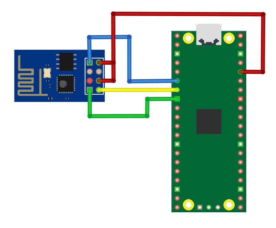 From the pinouts you should be able to work out the way the ESP8266 has to be connected. If we use GP4 as Tx from the Pico and GP5 as Rx to the Pico we have to connect ESP-01 pin 7 to GP4, pin 2 to GP5 and pins 8 and 4 to the power supply. To make it all work we also have to connect pin 1 to the ground.