| Introduction to Boolean Logic |
| Written by Mike James |
| Tuesday, 11 March 2025 |
|
Page 3 of 7
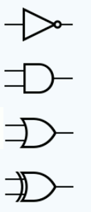
From Truth Tables to Electronic CircuitsNot only does this little demonstration illustrate why Boolean logic is useful in designing such systems, it also explains why electronics circuits to perform Boolean logic are commonplace. You can buy integrated circuits that perform AND, OR and NOT and many other combinations of these operations in a single easy to use package. Where is the “truth” in this? Clearly Boolean logic works with “true” and “false” and this is certainly how Boole himself thought about it, but you can work with the same system of operators and results no matter what you call the two states - up/down, on/off or zero/one. In the electronics case it is more natural to think of high and low voltage as representing the natural states that we are working with. An explanation that involves Boolean logic often sounds more appropriate when expressed in terms that belong to the underlying subject matter but it is still the same Boolean logic. What has all of this got to do with computers? The answer is two-fold. The first connection is that computers contain electronic circuitry that behaves in much the same way as the burglar alarm. In general, Boolean logic helps when you need to design a circuit that has to give an output only when certain combinations of inputs are present. Such a circuit uses “combinatorial logic” and there are lots of them inside a computer. You can specify the behavior of any piece of combinatorial logic using a truth table. The only difference is that in most cases the tables are very large and converting them into efficient hardware is quite a difficult job. Logic in HardwareWhat makes Boolean logic so central to computers and a wide range of electronic devices is that logic is easy to implement. A logic "gate" is a piece of electronics that takes in some inputs and produces an output according to one of the logic tables. Usually the inputs are either high or low and this is interpreted as 1 and 0 or “true” and “false”. For example, a NOT gate has a single input and its output is high when its input is low, and vice versa. You can create more complicated logic circuits by wiring up gates. The standard symbols for the three basic logic gates - NOT, AND and OR plus the XOR are:
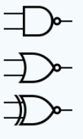
In general, a small circle on a connection indicates a negation or a NOT. For example, the symbols for NAND, NOR and XNOR, the negation of XOR are : :
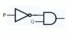
In many ways this is electronics made easy. You don't need to know anything about transistors or other components to build a logic circuit. Just work out what the logical expression is and wire gates up to implement it. For example, our burglar alarm example has the logical expression: R = NOT(P) AND Q So to implement it in hardware we need a NOT gate and an AND gate:
Real logic circuits are much more complicated than this and can make use hundreds or even thousands of gates. |
| Last Updated ( Tuesday, 11 March 2025 ) |


