| Exploring Edison - Life At 1.8V |
| Written by Harry Fairhead | ||||
| Monday, 04 January 2016 | ||||
Page 1 of 3 One of the big problems with using the Edison, or so many believe, is that in its "raw" form it works with 1.8V logic. In practice this isn't as big a problem as you might imagine. Often you don't have to do anything and when you do it is an easy and cheap fix. This is a chapter from our ebook on the Intel Edison. The full contents can be seen below. Notice this is a first draft and a work in progress. Use the comments or email harry.fairhead@i-programmer.info with your queries or suggestions.
Now On Sale!You can now buy a print edition of Exploring Intel Edison.You can buy it from:
USA and World Amazon.com Chapter List
<ASIN:1871962447>
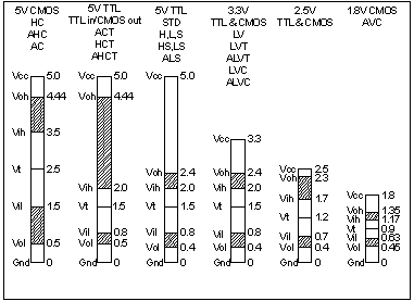
The Edison works with 1.8V logic. When you use it with the Arduino breakout board then there are logic level converters that save you from having to worry about this. If you want to make the best use of the Edison then you certainly have to avoid the Arduino breakout board and use the mini breakout board. However the mimi breakout board doesn't buffer or level shift the raw GPIO lines of the Edison. This means that you either have to find sensors and transducers that work with 1.8V logic or you have to implement level shifters of your own. Once you have done this a few time it becomes very easy and it is very cheap. The following descriptions of how things work are aimed at the reader who knows about basic physics - Ohm's Law say - but isn't an electronics expert. Logic LevelsAll logic implementation have a range of voltages that are regarded as a zero and a one. These are important specifications that you need to know to make sure that your implementation of logic or logic level shifting works in a wide range of situations. The diagram below summarizes the logic levels for the most commonly encountered systems.
In each case the important numbers are Vih, Vil and Voh, Vol which give you the voltage range the inputs and outputs work with. For example for 1.8V logic Vih and Vil are 1.17V and 0.63V. That is if the input is 1.17V or greater it reads a one and if it is 0.63 or lower it reads a zero. The Voh and Vol figures give you the limits on the ouputs of the logic family. For example for 1.8V logic Voh is 1.35 and Vol is 0.45. What this means is that any 1.8V device will output at least 1.35V for a one and at most 0.45V for a zero. You can see that these figures give you a margin of tolerance. It the output is low then it will be at most 0.45V and this is below the 0.63V needed by Vil which reads it as a zero. The Edison specification gives Vil as 0.35*Vdd and Vol as 0.45V which is exactly the standard as long as Vdd is 1.8V. Of course your level shifters and custom logic and aim for 1.8V for a one and 0V for a zero but the logic voltage levels tell you how accurate you have to be and what you can expect from the standard logic in the worst case. Output 1.8V To 3.3V and 5VFor output level conversion the key figures are Voh and Vol. The GPIO line will be at least 1.35V when high and not more than 0.45V for a low. As we are talking about voltage levels there is a tendency to immediately think that a voltage controlled device such as a MOSFET is the obvious choice. However the difficulty is finding a MOSFET with a gate threshold voltage in the correct range. Most general purpose MOSFETs have too high a threshold voltage to be turned on by 1.8V. Even if you find a MOSFET with a gate threshold voltage of 1.8V on average it is not going to be turned on sufficiently by the 1.8V on the GPIO line in the best case and in the worse case the GPIO line might be as low as 1.3V and the MOSFET gate threshold could be 2V or more. Also note that the gate threshold is the minimum voltage need to make the MOSFET just start to conduct. There are specially made N Channel MOSFETS for use in 1.8V logic circuits. For example, the FDN327B is marketed as a 1.8V logic MOSFET. Its characteristics are: VGS(th) Gate Threshold Voltage min 0.4 avg 0.7 max 1.5 V Equally important is the figure: RDS(ON) = 120 mΩ @ VGS = 1.8 V which is the MOSFETS resistance at a gate voltage of 1.8V. A typical MOSFET has a higher on resistance at its quoted gate threshold voltage. You can see that in this case it is low enough to conduct a reasonable current at 3.3V or 5V. Any MOSFET that you plan to use for a 1.8V level converter has to have parameters similar to or better the FDN327B. One big problem with the 1.8V MOSFETs is that they are generally surface mount components. This is not a huge problem in that in many case this is exactly what you want but it does make prototyping more difficult. If you want to use such MOSFETs then your choices are to buy a device pre-mounted on a breakout board, use a general purpose breakout board or solder some wires to the surface mount contacts. A good alternative to a MOSFET is an "old fashioned" Bipolar Junction Transistor - a BJT. The BJT often gets left out of introductory electronics courses because it is a current controlled device and this is more difficult to understand and work with. However in this case it has a big advantage. If you think of the silicon BJT as a simple 3-terminal switch then it switches on when the base reaches 0.6V relative to the emitter. If you compare this to the 1.8V logic thresholds you can see that it is a good fit and what is more any silicon npn transistor works in this way. That is you can use almost any general purpose npn transistor to convert 1.8V logic to 3.3V or 5V logic. In the rest of this chapter the 2N2222 transistor is used because it is common, cheap and available in a range of packages including through-hole, making it easy to use for prototyping. |
||||
| Last Updated ( Wednesday, 11 May 2016 ) |

