Exploring Edison - First Contact
Written by Harry Fairhead   
Friday, 12 June 2015
Article Index
Exploring Edison - First Contact
Configuring the Serial Port
Controlling and Edison GPIO Pin

There is no avoiding the fact that if you are going to work with the Edison and get something special out of it then you are going to have to go native.  In this installment of Exploring Edison, we get connected to Linux on both the Arduino and mini-breakout boards.


This is a chapter from our ebook on the Edison. The full contents can be seen below. Notice this is a first draft and a work in progress. 


ExploringEdison


Now On Sale!

You can now buy a print edition of Exploring Intel Edison.
You can buy it from:
 

USA and World  Amazon.com
Canada              Amazon.ca
UK                      Amazon.co.uk
France                Amazon.fr
Germany            Amazon.de
Spain                  Amazon.es
Brazil                  Amazon.br
Italy                    Amazon.it
Japan                 Amazon.co.jp
Mexico               Amazon.com.mx 


Chapter List

  1. Meet Edison
    In this chapter we consider the Edison's pros and cons and get an overview of its structure and the ways in which you can make use of it. If you have ever wondered if you need an Edison or an Arduino or even a Raspberry Pi then this is the place to start. 

  2. First Contact
    When you are prototyping with the Edison you are going to need to use one of the two main breakout boards - the Arduino or the mini. This chapter explains how to set up the Edison for both configurations. 

  3. In C
    You can program the Edison in Python, JavaScript or C/C+ but there are big advantages in choosing C. It is fast, almost as easy as the other languages and gives you direct access to everything. It is worth the effort and in this chapter we show you how to set up the IDE and get coding. 

  4. Mraa GPIO
    Using the mraa library is the direct way to work with the GPIO lines and you have to master it. Output is easy but you do need to be aware of how long everything takes. Input is also easy but using it can be more difficult. You can use polling or the Edison interrupt system which might not work exactly as you would expect.

  5. Fast Memory Mapped I/O
    There is a faster way to work with GPIO lines - memory mapped I/O. Using this it is possible to generate pulses as short at 0.25 microsecond and read pulse widths of 5 microseconds. However getting things right can be tricky. We look at how to generate fast accurate pulses of a given width and how to measure pulse widths.

  6. Near Realtime Linux 
    You need to be aware how running your programs under a non-realtime operating system like Yocto Linux effects timings and how accurately you can create pulse trains and react to the outside world. In this chapter we look the realtime facilities in every version of Linux. 

  7. Sophisticated GPIO - Pulse Width Modulation 
    Using the PWM mode of the GPIO lines is often the best way of solving control problems. PWM means you can dim an LED or position a servo and all using mraa. 

  8. Sophisticated GPIO -  I2C 
    I2C is a simple communications bus that allows you to connect any of a very large range of sensors. 

  9. I2C - Measuring Temperature  
    After looking at the theory of using I2C here is a complete case study using the SparkFun HTU21D hardware and software. 
     
  10. Life At 1.8V
    How to convert a 1.8V input or output to work with 5V or 3.3V including how to deal with bidirectional pull-up buses.

  11. Using the DHT11/22 Temperature Humidity Sensor at 1.8V 
    In this chapter we make use of all of the ideas introduced in earlier chapters to create a raw interface with the low cost DHT11/22 temperature and humidity sensor. It is an exercise in interfacing two logic families and implementing a protocol directly in C. 

  12. The DS18B20 1-Wire Temperature 
    The Edison doesn't have built in support for the Maxim 1-Wire bus and this means you can't use the very popular DS18B20 temperature sensor. However with a little careful planning you can and you can do it from user rather than kernel space. 

  13. Using the SPI Bus 
    The SPI bus can be something of a problem because it doesn't have a well defined standard that every device conforms to. Even so, if you only want to work with one specific device it is usually easy to find a configuration that works - as long as you understand what the possibilities are. 

  14. SPI in Practice The MCP3008 AtoD 
    The SPI bus can be difficult to make work at first, but once you know what to look for about how the slave claims to work it gets easier. To demonstrate how its done let's add eight channels of 12-bit AtoD using the MCP3008.

  15. Beyond mraa - Controlling the features mraa doesn't. 
    There is a Linux-based approach to working with GPIO lines and serial buses that is worth knowing about because it provides an alternative to using the mraa library. Sometimes you need this because you are working in a language for which mraa isn't available. It also lets you access features that mraa doesn't make available. 
 

<ASIN:1871962447>


 edisonsd


Which Breakout Board

As explained in more detail in Choosing a Breakout Board, the Arduino breakout board isn't the lightest weight option for working with the Edison but it is very capable. It provides lots of I/O expansion, works with more familiar logic voltage levels and if you have a working knowledge of the Arduino there is very little extra to learn. 

edisonarduinoreal

However, the Edison plus the Arduino breakout board isn't exactly an Arduino - it is more than an Arduino because it is a full Linux machine as well. So there are many new things to learn.

The native mini-breakout board is harder to work with in some respects but it is the one you need to master to get the real Edison experience. 


edisonbreakoutral

in this chapter of Exploring Edison we work through the ideas need to get started with the Arduino and the mini-breakout board. 

The mini-breakout board is the one that brings out the true nature of the Edision but the Arduino board is useful for checking that software works and gaining access to extended I/O without having to implement any special hardware. 

The Hardware

Setting up the Edison with either of the Intel breakout boards is fairly straightforward and there isn't much that you have to do. 

Get the Edison and plug it into the breakout board. Fix it into place using the nuts provided if you don't plan to remove it often. 

For the Arduino board you can also screw in the plastic spacers if you really feel the need to. They only serve to lift the board up from the working surface.

The next step is to find two USB cables (Micro B to A) or one USB cable and a power supply. When you are getting started it is probably easier to use the two USB cables as this powers the Edison and gives you access to its internal storage and other facilities. 

At this point the question arises of why two cables. 

The answer is that the breakout boards both have two USB connectors.

One of the connectors - the one on the inside - is a true USB port.

The other - the one on the edge - is a serial interface converted to be a USB port. 


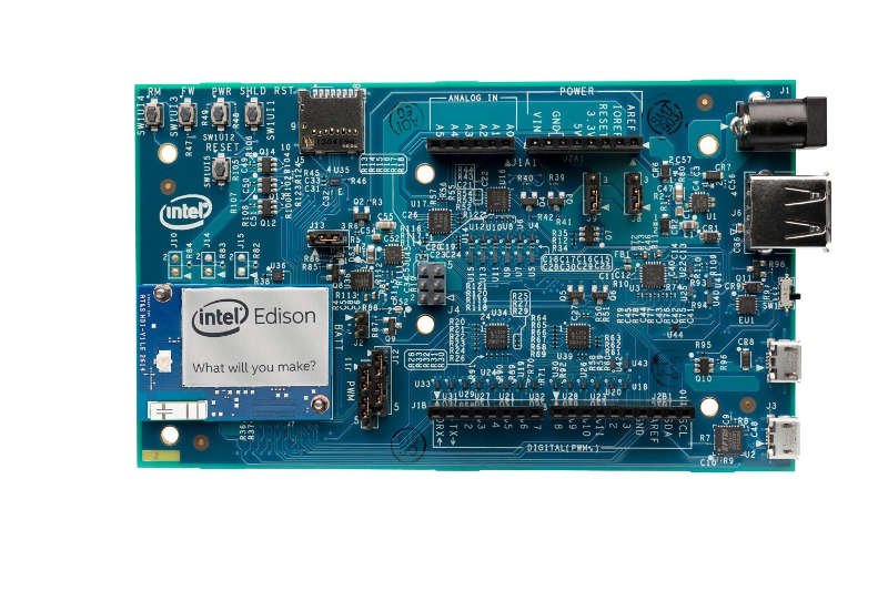
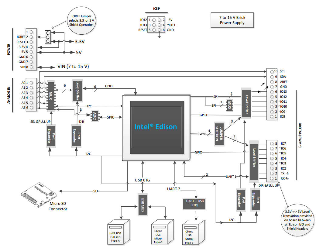
You can see the USB connections at the bottom of the block diagram on the Arduino breakout board.

Arduinobreakout 

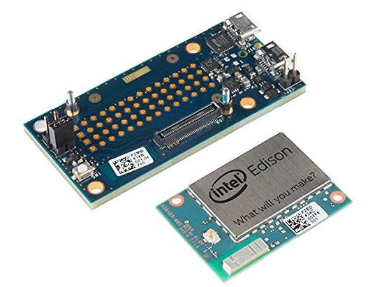
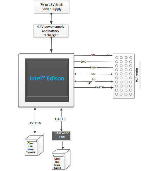
and the two USB connections on the mini-breakout board:

edisonbreakout


The true USB port can be used to power the system and it allow you to make a connection for doing things like downloading software and access the Edison's internal storage. 

The Serial USB port is used to connect a serial console so that you can "talk" to the Linux operating system. 

In practice you avoid using one of the two USB connections but when you are starting it is best to just make use of them for simplicity of getting started.

The only thing you have to make sure of on the Arduino board is the position of the micro switch between the big USB A socket and the micro USB socket is pushed over towards the micro socket. 

The big A socket and the micro USB socket share the same USB port and the switch selects which one is active. The A socket allows the Edison to be a host and power and control other USB devices. The micro socket is always a client.


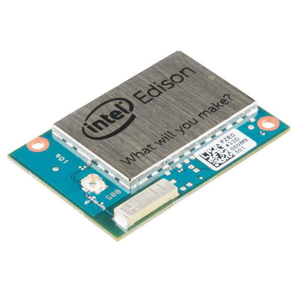
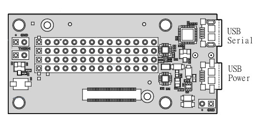
On the mini-breakout board the sockets are easy to find:

mini


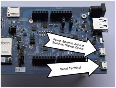
On the Arduino board they are also fairly obvious:

arduino


So all you have to do is plug two USB cables into the breakout board and into a suitable computer. 

If you do this you should see a green LED next to the Edison light up to indicate that power is on. 

Depending on the OS you are using various drivers may have been automatically installed or you may have install them manually. 

One thing that does get installed automatically on all systems is the Edison's internal drive. If everything is working you should be able to see an additional drive labeled "Edison" in what ever file manger you are using.

Let's deal in detail with the serial port first and start talking to the on board Yocto Linux.

At this stage you can more or less ignore the other USB socket and just treat it as a way of supplying power. You don't even have to install drivers for it until you want to make use of it. 

<ASIN:B00ND1KH42@COM>

<ASIN:B00ND1KNXM>

<ASIN:B00OPTSZN6@UK>


Last Updated ( Sunday, 19 July 2015 )