|
Page 1 of 4 The mraa C library is the most direct way to get in touch with the Intel Edison's GPIO lines. In this chapter we take a look at the basic operations of input and output, examine GPIO read/write timing, and learn how to use interrupt handling to improve performance when detecting changes in input readings.
This is a chapter from our ebook on the Intel Edison. The full contents can be seen below. Notice this is a first draft and a work in progress.
Now On Sale!
You can now buy a print edition of Exploring Intel Edison.
You can buy it from:
USA and World Amazon.com
Canada Amazon.ca
UK Amazon.co.uk
France Amazon.fr
Germany Amazon.de
Spain Amazon.es
Brazil Amazon.br
Italy Amazon.it
Japan Amazon.co.jp
Mexico Amazon.com.mx
Chapter List
-
Meet Edison
In this chapter we consider the Edison's pros and cons and get an overview of its structure and the ways in which you can make use of it. If you have ever wondered if you need an Edison or an Arduino or even a Raspberry Pi then this is the place to start.
- First Contact
When you are prototyping with the Edison you are going to need to use one of the two main breakout boards - the Arduino or the mini. This chapter explains how to set up the Edison for both configurations.
- In C
You can program the Edison in Python, JavaScript or C/C+ but there are big advantages in choosing C. It is fast, almost as easy as the other languages and gives you direct access to everything. It is worth the effort and in this chapter we show you how to set up the IDE and get coding.
- Mraa GPIO
Using the mraa library is the direct way to work with the GPIO lines and you have to master it. Output is easy but you do need to be aware of how long everything takes. Input is also easy but using it can be more difficult. You can use polling or the Edison interrupt system which might not work exactly as you would expect.
- Fast Memory Mapped I/O
There is a faster way to work with GPIO lines - memory mapped I/O. Using this it is possible to generate pulses as short at 0.25 microsecond and read pulse widths of 5 microseconds. However getting things right can be tricky. We look at how to generate fast accurate pulses of a given width and how to measure pulse widths.
- Near Realtime Linux
You need to be aware how running your programs under a non-realtime operating system like Yocto Linux effects timings and how accurately you can create pulse trains and react to the outside world. In this chapter we look the realtime facilities in every version of Linux.
- Sophisticated GPIO - Pulse Width Modulation
Using the PWM mode of the GPIO lines is often the best way of solving control problems. PWM means you can dim an LED or position a servo and all using mraa.
- Sophisticated GPIO - I2C
I2C is a simple communications bus that allows you to connect any of a very large range of sensors.
- I2C - Measuring Temperature
After looking at the theory of using I2C here is a complete case study using the SparkFun HTU21D hardware and software.
- Life At 1.8V
How to convert a 1.8V input or output to work with 5V or 3.3V including how to deal with bidirectional pull-up buses.
- Using the DHT11/22 Temperature Humidity Sensor at 1.8V
In this chapter we make use of all of the ideas introduced in earlier chapters to create a raw interface with the low cost DHT11/22 temperature and humidity sensor. It is an exercise in interfacing two logic families and implementing a protocol directly in C.
-
The DS18B20 1-Wire Temperature
The Edison doesn't have built in support for the Maxim 1-Wire bus and this means you can't use the very popular DS18B20 temperature sensor. However with a little careful planning you can and you can do it from user rather than kernel space.
- Using the SPI Bus
The SPI bus can be something of a problem because it doesn't have a well defined standard that every device conforms to. Even so, if you only want to work with one specific device it is usually easy to find a configuration that works - as long as you understand what the possibilities are.
- SPI in Practice The MCP3008 AtoD
The SPI bus can be difficult to make work at first, but once you know what to look for about how the slave claims to work it gets easier. To demonstrate how its done let's add eight channels of 12-bit AtoD using the MCP3008.
- Beyond mraa - Controlling the features mraa doesn't.
There is a Linux-based approach to working with GPIO lines and serial buses that is worth knowing about because it provides an alternative to using the mraa library. Sometimes you need this because you are working in a language for which mraa isn't available. It also lets you access features that mraa doesn't make available.
<ASIN:1871962447>
The mraa library is designed to smooth out the differences between hardware. In this case hardware includes the breakout board type as well as the CPU.
The Edison with the Arduino breakout board is complicated because some of the raw pins are used for more than one thing - they are multiplexed - and there is a lot of extra hardware connected to the raw pins for analog I/O for example. Mraa provides a simple interface to this complicated mess and make it look as if the Arduino "shield" I/O lines are simple GPIO lines.
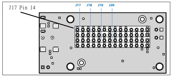
The mini-breakout board simply delivers the raw I/O lines to the connectors with no processing of any kind. This makes the task of the mraa library much simpler. The mraa pin numbers map directly to physical pins on the connector and correspond to simple GPIO lines.
You can argue that the mraa library really only comes into its own when the breakout board needs to be configured as well as the raw GPIO lines but as it already exists it is an easy and standard way to work with the native Edison hardware.
In this chapter we take a first look at using mraa to control the GPIO pins as basic input output lines.
In the next chapter we tackle the problem of making GPIO fast enough to do some "bit banging" that is low level protocols implemented in C. To do this we need to look at how to make Linux a "near" real time operating system.
If you know all about the basics of GPIO use including the subtleties of interrupt handling then jump to the next chapter.
Pin Numbering
The one thing that drives the Edison programmer mad is the different pin numberings in use. Basically there are three different pin numberings in use - Arduino, mraa and SYSFS. Of these the SYSFS number can be considered the "native" Edison GPIO numbering.
The Arduino pin numbering corresponds to standard Arduino shield pins. This is not in any way directly connected to the Edison GPIO numbering because multiple physical pins are used for different purposes on the Arduino breakout board. If you are using the min-breakout or anything that is closer to the real Edison hardware you can mostly ignore Ardunio pin numbering. The only time that it might be of concern is if you are trying to convert an Arduino sketch into C when you can look up which SYSFS number the pin corresponds to and then use the table given later to look up the corresponding mraa number.
The SYSFS pin numbers are the raw hardware defined GPIO lines that the Edison provides. In many ways you can consider these numbers to be reality. Linux exposes almost all external hardware as if it was a file system - character oriented like a terminal or block oriented like a disk. The GPIO lines are also provided to the user and programmer alike as a file system with each pin corresponding to an I/O stream. You can work directly with the GPIO by using Linux file commands and the pin numbering used is the standard hardware derived numbering.
Finally we have the mraa numbering which has nothing to do with anything as it is intended to provide a numbering that is independent of device and breakout board. Why this is an advantage is no entirely clear as most embedded programs target a specific platform and usually define things like pin numbers as constants at the start of the program. However if you are going to use mraa it is mraa's numbering you need to also use.
You can see the pin numberings in the table below. Don't worry about Pinmode 1 for the moment. By default we are working with the I/O pins setup as Pinmode 0 - more of this later.
In Pinmode 0 all of the lines are configured as digital I/O lines i.e. pure GPIO lines. In Pinmode 1 some of the pins have a special functions like PWM or I2C.
| MRAA Number | Physical Pin | Edison Pin
(SYSFS) | Pinmode0 | Pinmode1 |
|---|
| 0 |
J17-1 |
GP182 |
GPIO-182 |
PWM2 |
| 1 |
J17-2 |
NC |
|
|
| 2 |
J17-3 |
NC |
|
|
| 3 |
J17-4 |
VIN |
|
|
| 4 |
J17-5 |
GP135 |
GPIO-135 |
UART |
| 5 |
J17-6 |
RCVR_MODE |
|
|
| 6 |
J17-7 |
GP27 |
GPIO-27 |
I2C-6-SCL |
| 7 |
J17-8 |
GP20 |
GPIO-20 |
I2C-1-SDA |
| 8 |
J17-9 |
GP28 |
GPIO-28 |
I2C-6-SDA |
| 9 |
J17-10 |
GP111 |
GPIO-111 |
SPI-5-CS1 |
| 10 |
J17-11 |
GP109 |
GPIO-109 |
SPI-5-SCK |
| 11 |
J17-12 |
GP115 |
GPIO-115 |
SPI-5-MOSI |
| 12 |
J17-13 |
OSC_CLK_OUT_0 |
|
|
| 13 |
J17-14 |
GP128 |
GPIO-128 |
UART-1-CTS |
| 14 |
J18-1 |
GP13 |
GPIO-13 |
PWM1 |
| 15 |
J18-2 |
GP165 |
GPIO-165 |
|
| 16 |
J18-3 |
GPI_PWRBTN_N |
|
|
| 17 |
J18-4 |
MSIC_SLP_CLK2 |
|
|
| 18 |
J18-5 |
V_VBAT_BKUP |
|
|
| 19 |
J18-6 |
GP19 |
GPIO-19 |
I2C-1-SCL |
| 20 |
J18-7 |
GP12 |
GPIO-12 |
PWM0 |
| 21 |
J18-8 |
GP183 |
GPIO-183 |
PWM3 |
| 22 |
J18-9 |
NC |
|
|
| 23 |
J18-10 |
GP110 |
GPIO-110 |
SPI-5-CS0 |
| 24 |
J18-11 |
GP114 |
GPIO-114 |
SPI-5-MISO |
| 25 |
J18-12 |
GP129 |
GPIO-129 |
UART-1-RTS |
| 26 |
J18-13 |
GP130 |
GPIO-130 |
UART-1-RX |
| 27 |
J18-14 |
FW_RCVR |
|
|
| 28 |
J19-1 |
NC |
|
|
| 29 |
J19-2 |
V_V1P80 |
|
|
| 30 |
J19-3 |
GND |
|
|
| 31 |
J19-4 |
GP44 |
GPIO-44 |
|
| 32 |
J19-5 |
GP46 |
GPIO-46 |
|
| 33 |
J19-6 |
GP48 |
GPIO-48 |
|
| 34 |
J19-7 |
RESET_OUT |
|
|
| 35 |
J19-8 |
GP131 |
GPIO-131 |
UART-1-TX |
| 36 |
J19-9 |
GP14 |
GPIO-14 |
|
| 37 |
J19-10 |
GP40 |
GPIO-40 |
SSP2_CLK |
| 38 |
J19-11 |
GP43 |
GPIO-43 |
SSP2_TXD |
| 39 |
J19-12 |
GP77 |
GPIO-77 |
SD |
| 40 |
J19-13 |
GP82 |
GPIO-82 |
SD |
| 41 |
J19-14 |
GP83 |
GPIO-83 |
SD |
| 42 |
J20-1 |
V_VSYS |
|
|
| 43 |
J20-2 |
V_V3P30 |
|
|
| 44 |
J20-3 |
GP134 |
|
|
| 45 |
J20-4 |
GP45 |
GPIO-45 |
|
| 46 |
J20-5 |
GP47 |
GPIO-47 |
|
| 47 |
J20-6 |
GP49 |
GPIO-49 |
|
| 48 |
J20-7 |
GP15 |
GPIO-15 |
|
| 49 |
J20-8 |
GP84 |
GPIO-84 |
SD |
| 50 |
J20-9 |
GP42 |
GPIO-42 |
SSP2_RXD |
| 51 |
J20-10 |
GP41 |
GPIO-41 |
SSP2_FS |
| 52 |
J20-11 |
GP78 |
GPIO-78 |
SD |
| 53 |
J20-12 |
GP79 |
GPIO-79 |
SD |
| 54 |
J20-13 |
GP80 |
GPIO-80 |
SD |
| 55 |
J20-14 |
GP81 |
GPIO-81 |
SD |
You can see from the table that in the previous chapter we toggled mraa line 13 which is physically J17-14 and in Pinmode 0 Edison GPIO-128 as a SYSFS pin.
In most cases you can simply use the mraa pin number but if you want to use the Edison Pin number which corresponds to the Linux SYSFS pin number you can via the mraa_gpio_init_raw function which accepts SYSFS pin numbers. So you can change the init function to:
mraa_gpio_context pin = mraa_gpio_init_raw(128);
and still toggle the pin connected to J17-14.
The only reason for using SYSFS pin numbers is if you are converting a program written as a shell script.
Drive Characteristics
Each GPIO line can be configured as a general purpose I/O line.
For input the shortest pulse times that are recognized are given as:
- 100 ns for a 50 MHz clock when SoC is in S0 state.
- 260 ns for 19.2 MHz clock when SoC is in S0i1 or S0i2 State.
- 155.5 µs for 32 kHz clock (RTC) when SoC is in S0i3 State.
In most cases these smallest pulse widths are well below what can be measured using mraa.
In output mode each GPIO line can supply or sink 3mA.
|