|
Page 1 of 3 A point cloud is a set of points in a 3D space. You can view the cloud from different angles and lighting conditions. You can even apply colors and textures to its surfaces. A point cloud is one step away from a full 3D model and sometimes it is more useful.
Practical Windows Kinect in C#
Chapter List
- Introduction to Kinect
- Getting started with Microsoft Kinect SDK 1
- Using the Depth Sensor
- The Player Index
- Depth and Video Space
- Skeletons
- The Full Skeleton
- A 3D Point Cloud
One of the things that every Kinect programmer will be keen to try out is using the depth map to create a 3D point cloud. This is relatively easy in principle, but there are so many fine details you need to get right that it can be more difficult than you expect.
So far we have been plotting the depth field using 2D graphics, using color or brightness to give the depth of each pixel. Now we need to use the depth information supplied by the Kinect to construct a true 3D model of the scene.This can then be viewed in the usual way.
The first problem we have is deciding how to work with 3D using C#. There is no obvious choice for a 3D framework in managed code and the situation with Windows Forms is even more complicated and difficult. There is no official library to allow you to make use of DirectX from C#. Essentially there are two main choices - XNA or WPF. The details of using 3D are more or less the same between XNA and WPF and which is best depends on the rest of the application. In many ways WPF is the simpler of the two so let's start with it.
Basic WPF 3D
If you want an introduction to WPF 3D graphics then read Easy 3D which provides an example project which draws and animates a 3D cube. For our application we need a simple shape to create the plot of the point cloud. The reason we need simplicity is that WPF 3D isn't particularly efficient and if we plan to plot a point cloud based on a 320 x 240 depth map then we need to create over 76,000 3D objects. WPF tends to slow down at around 10,000 or so objects unless they are very simple.
To get the required performance, we will make use of a simple 2D triangle facet. This is enough to display the point cloud quite well but if you want something more complicated then you could try other solid shapes - you can see what happens when we use a cube later.
There are two main components to building a 3D scene - creating a 3D mesh complete with properties and setting up a camera to render the scene. Let's tackle these tasks in order.
The Triangle Surface
Start a new WPF project and add
using System.Windows.Media.Media3D;
Also use the designer to add a Canvas object and a Button to the form. The Canvas object will host our 3D view and the button will be used to start the code running.
We need to create a triangular surface to use in the 3D plot as a marker. To do this all we need are three points to define the triangle and a list of how these are connected together to form a mesh.
The Triangle method returns a GeometryModel3d object which contains a mesh and the properties to be applied to the mesh:
private GeometryModel3D Triangle(
            double x, double y,double s)
{
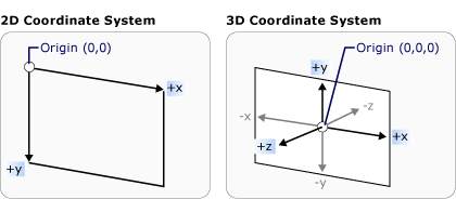
x and y give the position of the bottom corner and s is the size of the triangle's side. The 3D co-ordinate system has y increasing up the screen.

First we need to define the geometry as a set of points and the order that the points are connected up:
Point3DCollection corners =
                 new Point3DCollection();
corners.Add(new Point3D(x, y, 0));
corners.Add(new Point3D(x, y + s, 0));
corners.Add(new Point3D(x+s, y+s, 0));
Int32Collection Triangles =
                 new Int32Collection();
Triangles.Add(0);
Triangles.Add(1);
Triangles.Add(2);
Notice that the three points are listed in a anticlockwise order as viewed from the -z side of the axes and the triangle is at z=0. By definition the front face is the anticlockwise side of a facet and we plan to view this triangle from 0,0,0 looking into the positive z direction i.e. along the z axis towards points that have a +z coordinate. The reason this choice is made is so that the Kinect's depth measurements can be translated to 3D coordinates without any transformations.
Now that we have the geometry defined, we can create a MeshGeometry3D object
MeshGeometry3D tmesh =
                    new MeshGeometry3D();
tmesh.Positions = corners;
tmesh.TriangleIndices = Triangles;
It is also useful to define a direction that is at right angles to the front surface of the triangle - the normal vector. This is used in some types of lighting calculation.
tmesh.Normals.Add(new vector3D(0,0,-1));
Now all we have to do is to put the geometry together with some material properties and return the result:
 GeometryModel3D msheet =
                new GeometryModel3D();
 msheet.Geometry = tmesh;
 msheet.Material = new DiffuseMaterial(
        new SolidColorBrush(Colors.Red));
 return msheet;
}
A simple diffuse material in a single color is the simplest, and hence fastest, option.
|
