| Exploring Edison - SPI AtoD with the SPI Bus |
| Written by Harry Fairhead | |||||
| Monday, 20 June 2016 | |||||
Page 3 of 4
How FastOnce you have the basic facilities working the next question is always how fast does something work. In this case we need to know what sort or data rates we can achieve using this AtoD converter. The simplest way fo finding this out is to use the fastest read loop:
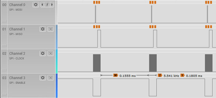
With a set clock frequency of 60KHz we get a measured clock rate of 60.1kHz the sampling rate is measured to be 1.6K sample/s which is less than the theoretical upper limit of 2.5K samples/s for 24 bits ignoring any dead time between readings. If you up the clock rate to 100KHz you will find that while the clock rate does go up to 100KHz the sample rate is only 2.3K samples/s compared to the theoretical upper limit of 4.16K samples/s. It doesn't matter how fast you attempt to push the clock rate, even to 1MHz you can't do better than about 5K samples/s which is a fundamental bottle neck set by the software.
Notice that it isn't possible to increase the speed by putting multiple reads into a single transfer because the MCP3008 simply sends zeros after the third byte if the master keeps the clock running. That is you can't use something like:
To get two readings from the device and so avoid the delays between each group of three bytes. Using Software SPI EmulationOne way of getting a higher sampling rate is to use the software emulation introduced at the end of the previous chapter. We could write a general n byte transfer function but as this is specifically aimed at reading the MCP3008 it makes more sense to write a function that transfers three bytes and reads the ADC returning the assembled value. First we need to add the global variables specifying the GPIO lines to use:
Next we need an initialization function and this is just the initialization code in the last chapter packaged into a function:
The read function is essentially the byte transfer function given at the end of the previous chapter but reading three bytes and only changing the CS1 line once a the start and end. The function starts off with some initialization and then it activates the CS1 line:
The first byte transfer is:
Notice we are not interested in what the ADC sends back to us so we can simply ignore the value in read. The second byte starts the data transfer and selects the ADC channel:
Notice that this time we collect the bottom two bits of the byte that the ADC sent and store them in result as the most significant bits. The final byte is the lower eight bits of the result:
Now all we have to do is deactivate the CS1 line and return the result:
If you try this out with:
you will discover that the clock rate is roughly 666KHz and the sample rate is roughly 24K samples per second. You can use lower sampling rates by setting a delay greater than zero. As before, notice that this tight sampling loop means that all other processes are locked out of running on the core that your program is running on. If you need to go faster than this, the only alternative at the moment is to use some external SPI hardware. Summary
|
|||||
| Last Updated ( Monday, 20 June 2016 ) |