| Exploring Edison - SPI |
| Written by Harry Fairhead | ||||||
| Thursday, 02 June 2016 | ||||||
Page 3 of 5
A Loop Back ExampleBecause of the way that data is transferred on the SPI bus it is very easy to test that everything is working without having to add any components. All you have to do is connect MOSI to MISO so that anything sent it also received in a loop back mode. First connect pin J17/12 to pin J18/11 using a jumper wire and start a new project. The program is very simple. First we initialize the SPI bus:
As this is a loop back test we really don't need to configure the bus, but for completeness:
Next we can send some data and receive it right back:
The hex value AA is useful in testing because it generates the bit sequence 10101010, which is easy to see on a logic analyser We can check that the received data matches the sent data in a variety of ways:
Finally we close the bus and the library:
Putting all of this together gives us the complete program:
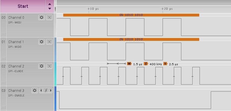
If you run the program and don't get the "data received correctly" message then the most likely reason is that you have connected the wrong two pins together or not connected them at all. Some Edison SPI ProblemsIf you connect a logic analyser to the four pins involved - J17-10,11 and 12 and J18-11 - you will see the data transfer:
If you look carefully you will see the CS0 line go low before the master places the first data bit on the MOSI and hence on the MISO lines. Notice that the clock rises in the middle of each data bit making this a mode 0 transfer. You can also see that the clock is measured to be 400KHz as promised. All as expected. However if you change the program to repeatedly send a single byte of data:
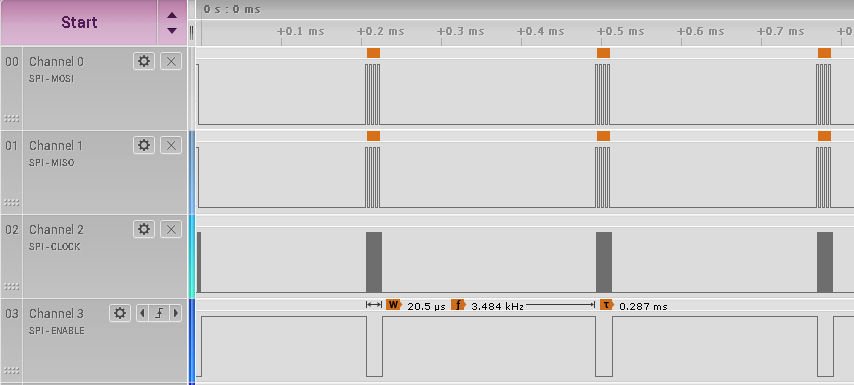
you will see something you might not have expected:
The clock rate may be specified as 400KHz, but the data rate is much slower. There is a .26ms delay between each byte transferred. This is not how SPI usually behaves. This is what Yocto Linux 3 does; before this the data rate was slowed down by the clock not starting for a long time after the CS line was active. The new behavior is much better and less likely to cause problems with SPI slaves. The delay effectively reduces the data rate to just less than 4.5K bytes/s from its theoretical upper limit of 50K bytes/s. What this means is that the data rate isn't as dependent on the clock speed as you might expect: 1MHz 5K bytes/s 400KHz 4.49K bytes/s 200KHz 3.8K bytes/s 100KHz 3.24K bytes/s 50KHz 2.43K bytes/s 10KHz 0.83K bytes/s The reason for this behavior is simply the overheads in calling the SPI functions to send a single byte. Earlier versions of Yocto Linux showed the same data transfer rates, but the slowdown was achieved by putting a delay in after the CS line had been activated. You might think that the way to get a higher data rate is to use one of the buffer transfer functions which don't toggle the CS line between each byte or word and which run the clock continuously. However, if you try this with Yocto Linux 3 you will find that its behaviour is a little strange. For example, the program:
transfers 1000 bytes containing 0,1,2,3,4 and so on and then compares the received data. You will find that you get error messages for all values after the first if the clock frequency is lower than about 800KHz If you reduce the number of bytes sent to three or fewer then it does work. If you use a clock frequency of 800KHz to less than 1MHz then it works but the clock speed is less than set. At 1MHz it works correctly and the clock speed is 1MHz with occasional pauses giving a data transfer rate of around 0.125Mbytes/s At 2Mhz it is 0.26Mbytes/s , 10MHz gives 1.6Mbytes/s and at 25MHz the transfer rate is 3.12Mbytes/s. However you have to keep the buffer size to less than around 5Kbytes or there are over run errors. The latest version of the SPI driver has changed to make use of DMA data transfer - hence the much higher speeds achievable. If you select a clock speed lower than 1MHz then the DMA seems to get out of sync with the bus. The documentation also says:
This means that multiple frame transfers only support Modes 1 and 3 and the CS line my be toggled between frames in modes 0 and 4. A User Mode DriverThe SPI bus doesn't seem able to do data transfers with a clock much slower than 1MHz. This is good for fast devices such as video displays but some devices can't work this fast. There is also the problem of supporting more SPI devices than the Edison hardware supplies. We can solve some of these problems with a software emulation of the SPI bus. The good news is that the SPI protocol is very simple. We will implement a mode 0 transfer of a single byte. The code presented is very simple and you could improve it a lot at the cost of clarity and perhaps, if you are not careful, speed. The SPI protocol in mode 0 with CS active low and SCK active high is:
You can see that we are setting the data just after the falling edge of the clock and reading the data just after the rising edge. |
||||||
| Last Updated ( Thursday, 02 June 2016 ) |