| The Pico In MicroPython: ADC |
| Written by Mike James & Harry Fairhead | ||||||||||||||||||
| Monday, 13 March 2023 | ||||||||||||||||||
Page 2 of 3
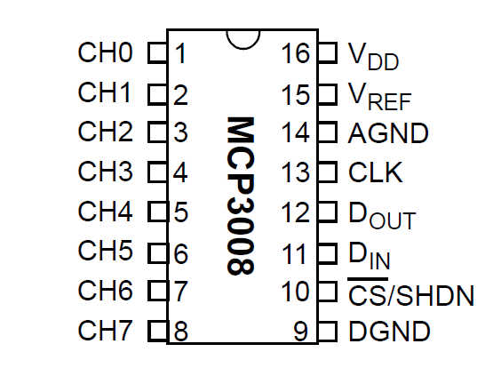
The MCP3008 SPI ADCAn alternative to using the Pico’s built-in ADC with its noise and stability problems is to use an external chip. The MCP3000 family is a low-cost versatile SPI-based set of A‑to‑D converters. Although the MCP3008, with eight analog inputs at 10-bit precision, and the MCP3004, with four analog inputs at 10-bit precision, are the best known, there are other devices in the family, including ones with 12-bit and 13-bit precision and differential inputs, at around the same sort of cost - $1 to $2. In this chapter the MCP3008 is used because it is readily available and provides a good performance at low cost, but the other devices in the family work in the same way and could be easily substituted.
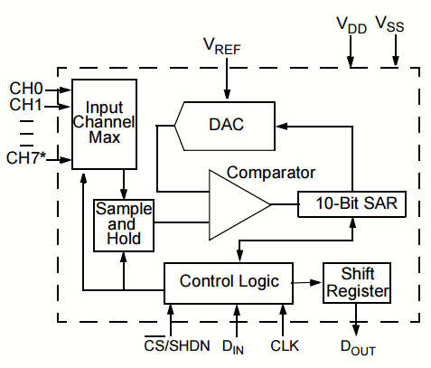
You need to take great care if you need high accuracy. For example, you will notice that there are two voltage inputs, VDD and VREF. VDD is the supply voltage that runs the chip and VREF is the reference voltage that is used to compare the input voltage. Obviously, if you want highest accuracy, VREF, which has to be lower than or equal to VDD, should be set by an accurate low-noise voltage source. However, in most applications VREF and VDD are simply connected together and the usual, low- quality, supply voltage is used as the reference. If this isn't good enough then you can use anything from a Zener diode to a precision voltage reference chip such as the TL431. At the very least, however, you should add a 1µF capacitor to ground connected to the VDD pin and the VREF pin. The MC3000 family is based on the same type of ADC as the Pico’s built-in device, a successive approximation converter.
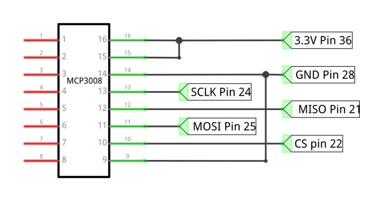
Also, to charge the capacitor quickly enough for it to follow a changing voltage, it needs to be connected to a low-impedance source. In most cases this isn't a problem, but if it is you need to include an op amp. If you are using an op amp buffer then you might as well implement an anti-aliasing filter to remove frequencies from the signal that are too fast for the ADC to respond to. How all this works takes us into the realm of analog electronics and signal processing and well beyond the core subject matter of this book. You can also use the A‑to‑D channels in pairs, i.e. in differential mode, to measure the voltage difference between them. For example, in differential mode you measure the difference between CH0 and CH1, i.e. what you measure is CH1-CH0. In most cases, you want to use all eight channels in single-ended mode. In principle, you can take 200k samples per second, but only at the upper limit of the supply voltage, i.e. VDD=5V, falling to 75k samples per second at its lower limit of VDD=2.7V. The SPI clock limits are a maximum of 3.6MHz at 5V and 1.35MHz at 2.7V. The clock can go slower, but because of the problem with the sample-and-hold mentioned earlier, it shouldn't go below 10kHz. How fast we can take samples is discussed later in this chapter. Connecting To The PicoThe connection from the MCP3008 to the Pico’s SPI bus is very simple and can be seen in the diagram below.
The only additional component that is recommended is a 1µF capacitor connected between pins 15 and 16 to ground, which is mounted as close to the chip as possible. As discussed in the previous section, you might want a separate voltage reference for pin 15 rather than just using the 3.3V supply. |
||||||||||||||||||
| Last Updated ( Wednesday, 15 March 2023 ) |