| Raspberry Pi IoT In C Using Linux Drivers - The I2C Linux Driver |
| Written by Harry Fairhead | |||||||||||||||||||||||||||||
| Monday, 25 July 2022 | |||||||||||||||||||||||||||||
Page 2 of 4
A Real Device - HTU21DUsing an I2C device has two problems - the physical connection between master and slave and figuring out what the software has to do to make it work. Here we’ll work with the SparkFun HTU21D/Si7021 and the information in its datasheet to make a working temperature and humidity sensor using the I2C functions we’ve just met. First the hardware. The HTU21D Humidity and Temperature sensor is one of the easiest of I2C devices to use. Its only problem is that it is only available in a surface-mount package. To overcome this you could solder some wires onto the pads or buy a general breakout board. However, it is much simpler to buy the SparkFun HTU21D breakout board because this has easy connections and built-in pull-up resistors. The HTU21D has been replaced by the Si7021 which is more robust than the original and works in the same way although the HTU21D is still available from many sources. If you decide to work with some other I2C device you can still follow the steps given, modifying what you do to suit it. In particular, if you select a device that only works at 5V you might need a level converter. It is worth noting that there is a specific Linux driver for the HTU21D. This is described in Chapter 14 and in most cases is the preferred way to use the device. To provide a generalizable example, here we look at exactly how the device works on the I2C bus and a program that interfaces with it at a low level is described. Wiring the HTU21DGiven that the HTU21D has pull-up resistors, we really should disable them for use on the Pi’s internal I2C bus which already has pull-ups. In practice, the additional pull-ups don't seem to make much difference to the waveforms and you can leave them in place while testing. You can use a prototype board to make the connections and this makes it easier to connect other instruments such as a logic analyzer.
A First ProgramAfter wiring up any i2C device the first question that needs to be answered is, does it work? Unfortunately for most complex devices finding out if it works is a multi-step process. Our first program aims to read some data back from the HTU21D - any data will do. If you look at the datasheet you will find that the device address is 0x40 and its supports the following commands/registers:
The easiest of these to get started with is the Read user register command, which gives the current setup of the device and can be used to set the resolution of the measurement. Notice that the codes that you send to the device can often be considered addresses or commands. In this case you can think of sending 0xE7 as a command to read the register or the read address of the register, it makes no difference. In most cases the term command is used when sending the code makes the device do something, and the term address is used when it simply makes the device read or write specific data. To read the user register we have to write a byte containing 0xE7 and then read the byte the device sends back. This involves sending an address frame, a data frame, and then another address frame and reading a data frame. The device seems to be happy if you send a stop bit between each transaction or just a new start bit.
A program to read the user register is fairly easy to put together. The address of the device is 0x40 so its write address is 0x80 and its read address is 0x81. As the I2C functions adjust the address as needed, we simply use 0x40 as the device's address, but it does affect what you see if you sample the data being exchanged: #define _DEFAULT_SOURCE
#include <stdio.h>
#include <stdlib.h>
#include <string.h>
#include <sys/ioctl.h>
#include <unistd.h>
#include <fcntl.h>
#include <linux/i2c-dev.h>
void checkI2CBus();
FILE * doCommand(char *cmd);
int main(int argc, char** argv) {
checkI2CBus();
int i2cfd = open("/dev/i2c-1", O_RDWR);
ioctl(i2cfd, I2C_SLAVE, 0x40);
char buf[4] = {0xE7};
write(i2cfd,buf,1);
read(i2cfd,buf,1);
printf("%x\n\r",buf[0]);
close(i2cfd
return (EXIT_SUCCESS);
}
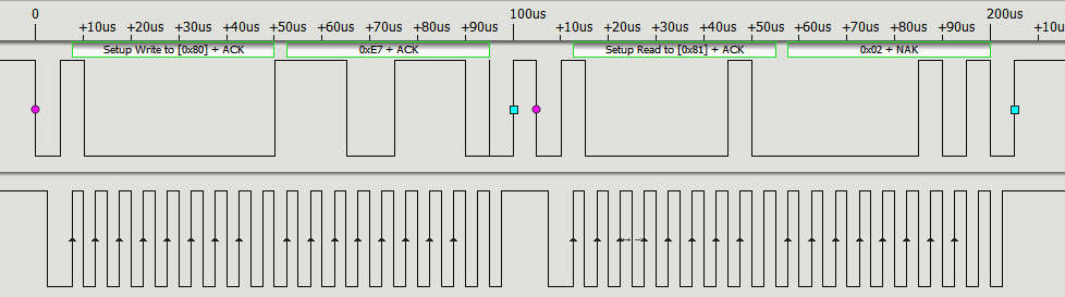
This sends the address frame 0x80 and then the data byte 0xE7 to select the user register. Next it sends an address frame 0x81 to read the data. If you run the program you will see “2”. This is the default value of the register and it corresponds to a resolution of 12 and 14 bits for the humidity and temperature respectively and a supply voltage greater than 2.25V. I2C Protocol In ActionIf you have a logic analyzer that can interpret the I2C protocol connected what you will see is:
You can see that the write_byte function sends an address packet set to the device's 7-bit address 0x40 as the high order bits with the low order bit set to zero to indicate a write, i.e 0x80. After this you get a data packet sent containing 0xE7, the address of the register. After a few microseconds it sends the address frame again, only this time with the low order bit set to 1 to indicate a read, i.e. it sends 0x81. It then receives back a single byte of data from the device, 0x02. This demonstrates that the external device is working properly and we can move on to getting some data of interest. |
|||||||||||||||||||||||||||||
| Last Updated ( Monday, 25 July 2022 ) |