| Raspberry Pi IoT In C - Basic Pulse Width Modulation |
| Written by Harry Fairhead | |||||
| Monday, 20 June 2022 | |||||
Page 3 of 4
Selecting Clock RateOne of the basic problems in using the Pi's PWM is selecting a clock divider and range value. There is a fairly standard way of doing this. The best way to work out a configuration that gives a particular repeat rate is to start at the highest clock rate, i.e. 9.6MHz, with a divider of 2 and work out the range needed. In general: max range = repeat time*clock frequency = repeat time* 9.6*1000 with the repeat time in milliseconds. For example, if you need a repeat rate of 5ms then: max range = 5 * 9.6 * 1000 = 48000 What this means is that the duty cycle can be specified using 16 bits of precision. Similarly if the repeat rate is specified as a frequency then max range is: max range = clock frequency/ repeat frequency = 9.6/repeat frequency This gives you the maximum range you can use. The previous example with a 5ms repeat time is equivalent to 0.2kHz and hence: max range = 9.6/0.2*1000 = 48000 which is of course the same range. If you want a smaller range you can reduce the clock to a lower frequency and the divider you need is: divider = 2* max range/desired range The 2 is because it is the smallest divider you can use. For example, if you want to reduce the range to 8 bits, i.e. range 255, but keep the repeat time at 5ms, you would need a divider given by: divider = 2 * 48000/255 = 367 The closest divider to this is 256 which gives a clock rate of 75kHz and a repeat rate of 3.1ms and a frequency of 294kHz, which isn't that close to the desired rate, but this is the best we can do if you are restricted to an 8-bit resolution for the duty cycle. Using PWMSo now you know how to make use of the PWM lines. All you have to do is set the frequency, range and data. You also have to set the mode of the GPIO pin that you are using the correct ALT mode, some GPIO lines have a number of alternative uses or ALT modes. In this case, to enable the two PWM pins, you set GPIO 18 to ALT 5 and GPIO 13 to ALT 0: bcm2835_gpio_fsel(18, BCM2835_GPIO_FSEL_ALT5); bcm2835_gpio_fsel(13, BCM2835_GPIO_FSEL_ALT0); The simplest PWM program you can write is: #include <bcm2835.h>
int main(int argc, char** argv) {
if (!bcm2835_init())
return 1;
bcm2835_gpio_fsel(18, BCM2835_GPIO_FSEL_ALT5);
bcm2835_pwm_set_clock(2);
bcm2835_pwm_set_mode(0, 1, 1);
bcm2835_pwm_set_range(0, 2);
bcm2835_pwm_set_data(0, 1);
return (0);
}
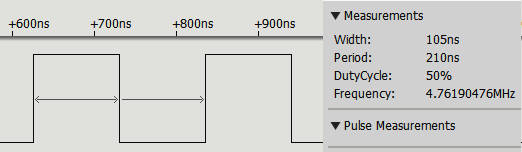
The clock is set to its fastest (9.6MHz) and PWM 0 is set to mark/space mode with range 2 and data 1. This produces the fastest pulse train with one clock pulse high and one low: The theoretical pulse width is 104.16ns and it is measured to be 105ns.
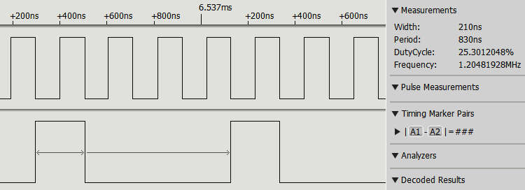
You have to set the value first and then set the period, otherwise the PWM line isn't set up properly. You also have to set the period for each pin you are using, even if it does set the same period. Notice that there is no need to put the program into an infinite loop. Once the PWM line has been set up and enabled, it just gets on with generating the pulse train, no matter what the processor does. In this case the pulse generation continues long after the program has ended. This may be fast, but as a PWM signal it is completely useless because you cannot change its duty cycle to anything useful. In practice, you need to set range to something greater than 2. Just to demonstrate that two PWM lines can be used independently of one another, here is a program that sets each one of the PWM GPIO lines to a different duty cycle and repeat rate: #include <stdio.h>
#include <stdlib.h>
#include <bcm2835.h>
int main(int argc, char **argv)
{
if (!bcm2835_init())
return 1;
bcm2835_gpio_fsel(18, BCM2835_GPIO_FSEL_ALT5);
bcm2835_gpio_fsel(13, BCM2835_GPIO_FSEL_ALT0);
bcm2835_pwm_set_clock(2);
bcm2835_pwm_set_mode(0, 1, 1);
bcm2835_pwm_set_range(0, 2);
bcm2835_pwm_set_data(0, 1);
bcm2835_pwm_set_mode(1, 1, 1);
bcm2835_pwm_set_range(1, 8);
bcm2835_pwm_set_data(1, 2);
return (EXIT_SUCCESS);
}
You can see the r |
|||||
| Last Updated ( Saturday, 25 June 2022 ) |