| The Pico In MicroPython: Simple Input |
| Written by Harry Fairhead & Mike James | |||
| Monday, 17 January 2022 | |||
Page 1 of 2 Input is difficult because the world can make it happen at any time and you have to be ready for it. Simple input isn't so simple. This is an extract from our book all about the Raspberry Pi Pico in MicroPython. Programming the Raspberry Pi Pico/W In MicroPython Second EditionBy Harry Fairhead & Mike James
Buy from Amazon. Contents
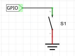
Also of interest: There is no doubt that input is more difficult than output. When you need to drive a line high or low you are in command of when it happens, but input is in the hands of the outside world. If your program isn't ready to read the input, or if it reads it at the wrong time, then things just don't work. What is worse, you have no idea what your program is doing relative to the event you are trying to capture. Welcome to the world of input. In this chapter we look at the simplest approach to input – the polling loop. This may be simple, but it is a good way to approach many tasks. In Chapter 8 we look at more sophisticated alternatives – events and interrupts. GPIO InputGPIO input is a much more difficult problem than output from the point of view of measurement and verification. For output at least you can see the change in the signal on a logic analyzer and know the exact time that it occurred. This makes it possible to track down timing problems and fine tune things with good accuracy. Input on the other hand is "silent" and unobservable. When did you read in the status of the line? Usually the timing of the read is with respect to some other action that the device has taken. For example, you read the input line 20µs after setting the output line high. But how do you know when the input line changed state during that 20 microseconds? The simple answer is in most cases you don’t. In some applications the times are long and/or unimportant but in some they are critical and so we need some strategies for monitoring and controlling read events. The usual rule of thumb is to assume that it takes as long to read a GPIO line as it does to set it. This means we can use the delay mechanisms that we looked at with regard to output for input as well. One common and very useful trick when you are trying to get the timing of input correct is to substitute an output command to a spare GPIO line and monitor it with a logic analyzer. Place the output instruction just before the input instruction and where you see the line change on the logic analyzer should be close to the time that the input would be read in the unmodified program. You can use this to debug and fine tune and then remove the output statement. Basic Input FunctionsThe Pin object can be set to input mode using the constructor: pin = Pin(22, Pin.IN) You can also set the direction to input using the init method: pin.init(mode=Pin.IN) Once set to input, the GPIO line is high impedance so it won’t take very much current, no matter what you connect it to. However, notice that the Pico uses 3.3V logic and you should not exceed this value on an input line. For a full discussion of how to work with input see the previous chapter. You can read the line’s input state using the value method: result=pin.value() Notice that this is an “overloaded” method. If you supply a value as a parameter then it attempts to set the value as output. If you don’t specify a value then it gets the GPIO level as a zero or a one. This is all there is to using a GPIO line as an input, apart from the details of the electronics and the small matter of interrupts. As introduced in the previous chapter you can also set the internal pull-up or pull-down resistors using one of: Pin.PULL_UP = 1 Pull-up resistor enabled Pin.PULL_DOWN = 2 Pull-down resistor enabled in the constructor or the init method. The pull-up/down resistors are between 50 and 80kΩ. The Simple ButtonOne of the most common input circuits is the switch or button. If you want another external button you can use any GPIO line and the circuit explained in the previous chapter. That is, the switch has to have either a pull-up or pull-down resistor either provided by you or a built-in one enabled using software. The simplest switch input program using an internal pull-up is: from machine import Pin
import time
pinIn = Pin(22, Pin.IN,Pin.PULL_UP)
pinLED = Pin(25, Pin.OUT)
while True:
if pinIn.value():
pinLED.on()
else:
pinLED.off()
time.sleep(0.5)
The program simply tests for the line to be pulled high by the switch not being closed and then sets GP25 high. As GP25 is connected the on-board LED it will light up while it is not pressed. Notice GP22 goes low to indicate that the switch is pressed. |
|||
| Last Updated ( Friday, 18 March 2022 ) |