| Pi IoT In Python Using Linux Drivers - I2C |
| Written by Harry Fairhead & Mike James | |||||
| Monday, 01 November 2021 | |||||
Page 3 of 4
Putting this into a complete program gives: import subprocess
import io
import fcntl
from time import sleep
checkI2CBus()
I2C_SLAVE=0x0703
fdr = io.open("/dev/i2c-1", "rb", buffering=0)
fdw = io.open("/dev/i2c-1", "wb", buffering=0)
fcntl.ioctl(fdr, I2C_SLAVE, 0x40)
fcntl.ioctl(fdw, I2C_SLAVE, 0x40)
fdw.write( bytearray([0xF3]))
while(True):
try:
data=fdr.read(3)
break
except:
sleep(0.01)
msb=data[0]
lsb=data[1]
crc=data[2]
print("msb=",msb," lsb=",lsb," crc=",crc)
fdw.close()
fdr.close()
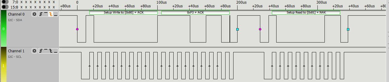
Where the checkI2CBus has been omitted as it was given earlier. If you try this out you should find that it works and it prints something like: msb 97 lsb 232 checksum 217 with the temperature in the 20C range. If you look at what is happening using a logic analyzer then you will see the initial interaction:
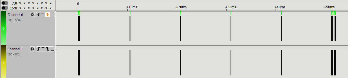
followed by repeated attempts to read the data:
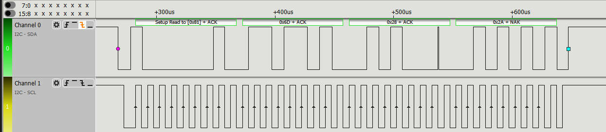
When the device is ready it responds with an ACK and the three data bytes are read:
You can also see that only one start and stop bit is used. Processing The DataOur next task isn't really directly related to the problem of using the I2C bus, but it is a very typical next step. The device returns the data in three bytes, but the way that this data relates to the temperature isn't simple. If you read the datasheet you will discover that the temperature data is the 14-bit value that results from putting together the most and least significant byte and zeroing the bottom two bits. The bottom two bits are used as status bits, bit zero currently isn't used and bit one is 1 if the data is a humidity measurement and 0 if it is a temperature measurement. To put the two bytes together we use: data16= (msb << 8) |(lsb & 0xFC) This zeros the bottom two bits, shifts the msb up eight bits and ORs the two together. The result is a 16-bit temperature value with the bottom two bits zeroed. Now we have raw temperature value but we have still have to convert it to standard units. The datasheet gives the formula: Temp in C = -46.85 + 175.72 * data16 / 2 16 As 216 is a constant that works out to 65536 it is more efficient to write: temp = -46.85 +(175.72 * data16 /65536) Now all we have to do is print the temperature: print("Temperature=",temp,"C")
Reading The HumidityThe nice thing about I2C and using a particular I2C device is that it gets easier. Once you have seen how to do it with one device, the skill generalizes and once you know how to deal with a particular device other aspects of the device are usually similar. Reading the humidity using polling is exactly the same as reading the temperature - all that changes is the command code we send: fdw.write( bytearray([0xF5]))
while(True):
try:
data=fdr.read(3)
print(data)
break
except:
sleep(0.01)
msb=data[0]
lsb=data[1]
crc=data[2]
Once we have the data the formula to convert the 16-bit value to percentage humidity is:
and the Python is: data16= (msb << 8) |(lsb & 0xFC)
hum = -6 + 125.0 * data16 / 65536
print("humidity=",hum,"%")
Checksum CalculationAlthough computing a checksum isn't specific to I2C, it is another common task. The datasheet explains that the polynomial used is: X8 + X5 + X4 + 1 Once you have this information you can work out the divisor by writing a binary number with a one in each location corresponding to a power of X in the polynomial. In this case the 8th, 5th, 4th and 1st bit. Hence the divisor is: 0x0131 What you do next is roughly the same for all CRCs. First you put the data that was used to compute the checksum together with the checksum value as the low order bits: data32 = (msb << 16)|(lsb <<8)| check Now you have three bytes, i.e 24 bits in a 32-bit value. Next you adjust the divisor so that its most significant non-zero bit aligns with the most significant bit of the three bytes. As this divisor has a 1 at bit eight it needs to be shifted 15 places to the right to move it to be the 24th bit: divisor = 0x988000 Now that you have both the data and the divisor aligned, you step through the top-most 16 bits, i.e. you don't process the low order eight bits which is the received checksum. For each bit you check to see if it is a 1 - if it is you replace the data with the data XOR divisor. In either case you shift the divisor one place to the right: for i in range(16):
if( data32 & 1<<(23 - i) ):
data32 ^= divisor
When the loop ends, if there was no error, the A complete function to compute the checksum is: def crcCheck(msb, lsb, check):
data32 = (msb << 16)|(lsb <<8)| check
divisor = 0x988000
for i in range(16):
        if( data32 & 1<<(23 - i) ):
            data32 ^= divisor
        divisor>>= 1
return data32
It is rare to get a CRC error on an I2C bus unless it is overloaded or subject to a lot of noise. |
|||||
| Last Updated ( Wednesday, 23 November 2022 ) |