|
Page 1 of 3 The Pico has a particularly flexible PWM generator but to get the most out of it you need to understand how it works. This is an extract from our latest book all about the Pico in C.
Programming the Raspberry Pi Pico In C
Third Edition
By Harry Fairhead

Buy from Amazon.
Contents
- Preface
- Chapter 1 The Raspberry Pi Pico – Before We Begin
- Chapter 2 Getting Started
- Chapter 3 Using GPIO Lines
- Chapter 4 Some Electronics
Extract: Erratum E9 Pull Down Problems ****NEW!
- Chapter 5 Simple Input
Extract: GPIO Input ***
- Chapter 6 Advanced Input – Events and Interrupts
- Chapter 7 Pulse Width Modulation
Extract: Basic PWM ***
- Chapter 8 Controlling Motors And Servos
- Chapter 9 Getting Started With The SPI Bus
- Chapter 10 A-To-D and The SPI Bus
- Chapter 11 Using The I2C Bus
- Chapter 12 Using The PIO
Extract: A 1-Wire PIO Program ***
- Chapter 13 The DHT22 Sensor Implementing A Custom Protocol
- Chapter 14 The 1‑Wire Bus And The DS1820
- Chapter 15 The Serial Port
- Chapter 16 Using the Pico W
Extract: Simple Web Client ***
Extract:A Better Connect ***
- Chapter 17 The Pico/W In C: Direct To Hardware *
- Chapter 18 Multicore and FreeRTOS
Extra: Adding WiFi To The Pico 2
*** Extracts from Edition 2 not yet updated.
One way around the problem of getting a fast response from a microcontroller is to move the problem away from the processor. In the case of the Pico there are some built-in devices that can use GPIO lines to implement protocols without the CPU being involved. In this chapter we take a close look at Pulse Width Modulation (PWM) including generating sound, driving LEDs and servos.
When performing their most basic function, i.e. output, the GPIO lines can be set high or low by the processor. How fast they can be set high or low depends on the speed of the processor.
Using the GPIO line in its Pulse Width Modulation (PWM) mode you can generate pulse trains up to 60MHz. The reason for the increase in speed is that the GPIO is connected to a pulse generator and, once set to generate pulses of a specific type, the pulse generator just gets on with it without needing any intervention from the GPIO line or the processor. In fact, the pulse output will continue after your program has ended.
Of course, even though the PWM line can generate pulses very fast pulses, usually what you want to do is change the nature of the pulses and this is a slower process involving the processor.
Some Basic Pico PWM Facts
There are some facts worth getting clear right from the start, although some of their significance will only become clear as we progress.
First, what is PWM? The simple answer is that a Pulse Width Modulated signal has pulses that repeat at a fixed rate - say one pulse every millisecond, but the width of the pulse can be changed.
There are two basic things to specify about the pulse train that is generated, its repetition rate and the width of each pulse. Usually the repetition rate is set as a simple repeat period and the width of each pulse is specified as a percentage of the repeat period, referred to as the duty cycle.
So, for example, a 1ms repeat and a 50% duty cycle specifies a 1ms period, which is high for 50% of the time, i.e. a pulse width of 0.5ms. The two extremes are 100% duty cycle, i.e. the line is always high, and 0% duty cycle, i.e. the line is always low.
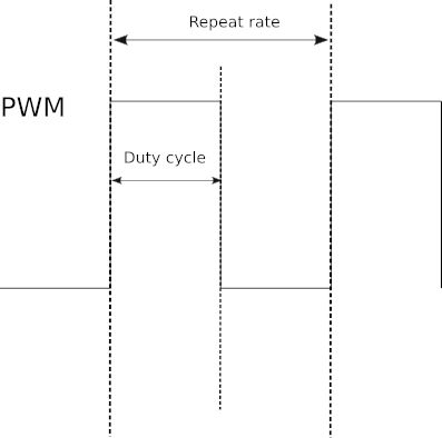
Notice it is the duty cycle that carries the information in PWM and not the frequency. What this means is that generally you select a repeat rate and stick to it and what you change as the program runs is the duty cycle.
In many cases PWM is implemented using special PWM-generator hardware that is built either into the processor chip or provided by an external chip. The processor simply sets the repeat rate by writing to a register and then changing the duty cycle by writing to another register. This generally provides the best sort of PWM with no load on the processor and, generally, glitch-free operation. You can even buy add-on boards that will provide additional channels of PWM without adding to the load on the processor.
The alternative to dedicated PWM hardware is to implement it in software. You can quite easily work out how to do this. All you need is to set a timing loop to set the line high at the repetition rate and then set it low again according to the duty cycle. You can implement this either using interrupts or a polling loop and in more advanced ways, such as using a DMA (Direct Memory Access) channel.
|