|
Page 1 of 3 Linux drivers make working with devices so easy - assuming you know how. Here's how to get a Raspberry Pi to get data from the 1-Wire Bus.
This content comes from our newly published book:
Raspberry Pi IoT In PythonUsing Linux Drivers
Second Edition
By Harry Fairhead & Mike James

Buy from Amazon.
Contents
- Choosing A Pi For IoT
- Getting Started With Python
- Drivers: A First Program
- The GPIO Character Driver
- GPIO Using Ioct ***NEW!!
-
GPIO Events
-
-
Some Electronics
-
Pulse Width Modulation Extract: PWM *
-
SPI Devices
-
I2C Basics Extract: I2C *
-
The I2C Linux Driver
-
Advanced I2C
-
Sensor Drivers
-
-
Going Further With Drivers
-
Appendix I
*From the first edition waiting for update.
<ASIN:B0CT46R6LF>
1-Wire Bus
The 1‑Wire bus is a proprietary protocol that is very easy to use and has a lot of useful devices you can connect to it, including the iButton security devices. However, probably the most popular of all 1‑wire devices is the DS18B20 Temperature Sensor - it is small, very cheap and very easy to use. This is the device that we are going to focus on in this chapter but the techniques generalize to working with any 1-wire device you care to use.
The Hardware
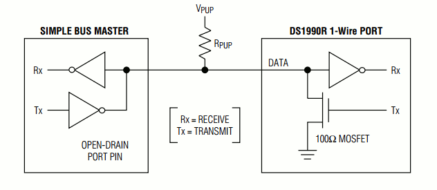
1-wire devices are very simple and only use a single wire, hence the name, to transmit data:

The 1‑wire device can pull the bus low using its Tx line and can read the line using its Rx line. The reason for the pull-up resistor is that both the bus master and the slave can pull the bus low and it will stay low until they both release the bus.
The device can even be powered from the bus line by drawing sufficient current through the pull-up resistor - so called parasitic mode. Low-power devices work well in parasitic mode, but some devices have such a heavy current draw that the master has to provide a way to connect them to the power line - so called strong pull-up. In practice parasitic mode can be difficult to make work reliably for high power devices.
In normal-powered mode there are just three connections - V power (usually 3.3V for the Pi), Ground, and Data:
 The pull-up resistor varies according to the device, but anything from 2.2K to 4.7kΩ works. The longer the bus the lower the pull-up resistor has to be to reduce “ringing”. There can be multiple devices on the bus and each one has a unique 64-bit lasered ROM code, which can be used as an address to select the active devices. The pull-up resistor varies according to the device, but anything from 2.2K to 4.7kΩ works. The longer the bus the lower the pull-up resistor has to be to reduce “ringing”. There can be multiple devices on the bus and each one has a unique 64-bit lasered ROM code, which can be used as an address to select the active devices.
The GPIO Driver
There are a number of drivers that implement the 1-Wire master, but the only one supported without extra work for the Raspberry Pi is the w1-gpio driver which implements the 1-Wire protocol on any GPIO pin that you aren’t using for something else. There is also the w1-gpio-pullup variant of the driver, which is only needed if you are driving a 1-Wire device over a long wire connection.
You can enable the 1-Wire driver using:
dtoverlay=w1-gpio,gpiopin=n
where n is the GPIO line you want to use. The default is GPIO4, but you really can use any GPIO line.
You can add this dtoverlay line to the /config/boot.txt file or you can enable it dynamically using:
def load1w(pin):
     indicator = "w1-gpio"
     command =["sudo", "dtoverlay",
                       "w1-gpio","gpiopin="+str(pin)]
     temp = subprocess.Popen(["sudo", "dtparam", "-l"],
                              stdout = subprocess.PIPE)
     output = str(temp.communicate())
     print(output,flush=True)
     if output.find(indicator)==-1:
        temp = subprocess.Popen(command,
                            stdout = subprocess.PIPE)
        output = str(temp.communicate())
        print(output,flush=True)
This just checks to see if there is an overlay currently active and if not it sets the pin you specify to be the 1-Wire bus.
As with all dynamic overlays, removing it isn’t a good idea and in the case of the 1-Wire driver, at the time of writing, it will crash the system. Once loaded, the overlay can stay active until the next reboot.
|


 The pull-up resistor varies according to the device, but anything from 2.2K to 4.7kΩ works. The longer the bus the lower the pull-up resistor has to be to reduce “ringing”. There can be multiple devices on the bus and each one has a unique 64-bit lasered ROM code, which can be used as an address to select the active devices.