| Pi IoT In C Using Linux Drivers - The SPI Driver |
| Written by Harry Fairhead | ||||
| Monday, 31 May 2021 | ||||
Page 2 of 3
Once you have the SPI interface set up, you can send and receive data using the SPI_IOC_MESSAGE request. This is slightly different from other requests in that a macro is used to construct a request that also specifies the number of operations needed. Each operation is defined by a struct: struct spi_ioc_transfer {
__u64 tx_buf;
__u64 rx_buf;
__u32 len;
__u32 speed_hz;
__u16 delay_usecs;
__u8 bits_per_word;
__u8 cs_change;
}
The fields are fairly obvious. The tx_buf and rx_buf are byte arrays used for the transmitted and received data – they can be the same array. The len field specifies the number of bytes in each array. The speed_hz field modifies the SPI clock. The delay_usecs field sets a delay before the chip select is deselected after the transfer. The cs_change field is true if you want the chip select to be deselected between each transfer. The best way to find out how this all works is to write the simplest possible example. A Loopback Example Because of the way that data is transferred on the SPI bus, it is very easy to test that everything is working without having to add any components. All you have to do is connect MOSI to MISO so that anything sent is also received in a loopback mode. There is an official example program to implement a loopback, but it is complicated for a first example and has a bug. Our version will be the simplest possible and, hopefully, without bugs. First connect pin 19 to pin 21 using a jumper wire and start a new project. The program is very simple. First we check that the SPI bus is loaded: checkSPI0(); and next we open spdev0.0: int fd = open("/dev/spidev0.0", O_RDWR);
As this is a loopback test we really don't need to configure the bus as all that matters is that the transmit and receive channels have the same configuration. However, we do need some data to send: uint8_t tx[] = {0xAA};
uint8_t rx[] = {0};
The hex value AA is useful in testing because it generates the bit sequence 10101010, which is easy to see on a logic analyzer. To send the data we need an spi_ioc_transfer struct: struct spi_ioc_transfer tr =
{
.tx_buf = (unsigned long)tx,
.rx_buf = (unsigned long)rx,
.len = 1,
.delay_usecs = 0,
.speed_hz = 500000,
.bits_per_word = 8,
};
We can now use the ioctl call to send and receive the data: int status = ioctl(fd, SPI_IOC_MESSAGE(1), &tr);
if (status < 0)
printf("can't send data");
Finally we can check that the send and received data match and close the file. Putting all of this together gives us the complete program: #define _DEFAULT_SOURCE
#include <stdio.h>
#include <stdlib.h>
#include <string.h>
#include <fcntl.h>
#include <unistd.h>
#include <sys/ioctl.h>
#include <linux/spi/spidev.h>
#include <stdint.h>
int main(int argc, char **argv)
{
checkSPI0();
uint8_t tx[] = {0xAA};
uint8_t rx[] = {0};
struct spi_ioc_transfer tr =
    {
        .tx_buf = (unsigned long)tx,
        .rx_buf = (unsigned long)rx,
        .len = 1,
        .delay_usecs = 0,
        .speed_hz = 500000,
        .bits_per_word = 8,
    };
int fd = open("/dev/spidev0.0", O_RDWR);
int status = ioctl(fd, SPI_IOC_MESSAGE(1), &tr);
if (status < 0)
        printf("can't send data");
printf("%X,%X", tx[0],rx[0]);
close(fd);
}
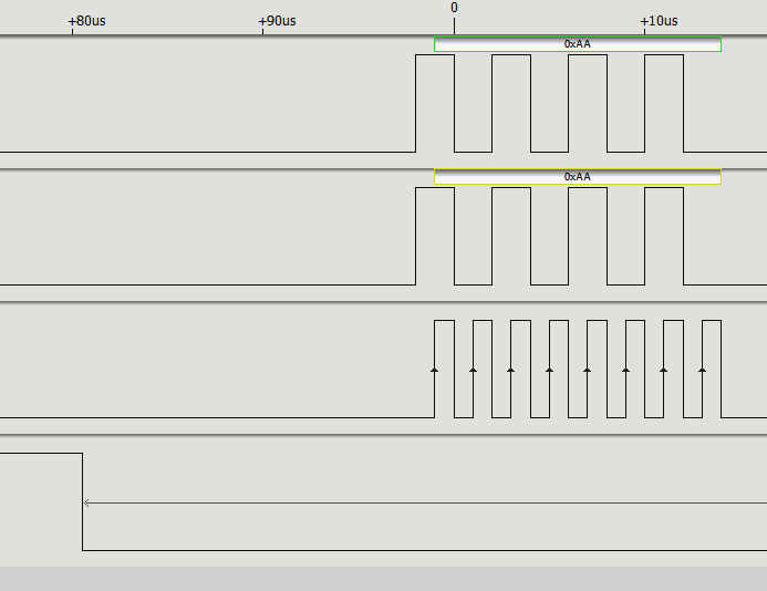
Note: The checkSPI0 function needs to be added to this listing. If you run the program and don't get any data, or receive the wrong data, then the most likely reason is that you have connected the wrong two pins, or not connected them at all. If you connect a logic analyzer to the four pins involved – 19, 21, 23 and 24 you will see the data transfer:
If you look carefully you will see the CS0 line go low before the master places the first data bit on the MOSI, and hence on the MISO, line. Notice that the clock rises in the middle of each data bit, making this a mode 0 transfer. If you need to configure the SPI interface you can use the ioctl calls. For example: static uint8_t mode = 1;
int ret = ioctl(fd, SPI_IOC_WR_MODE, &mode);
if (ret == -1)
printf("can't set spi mode");
static uint8_t bits = 8;
ret = ioctl(fd, SPI_IOC_WR_BITS_PER_WORD, &bits);
if (ret == -1)
printf("can't set bits per word");
static uint32_t speed = 500000;
ret = ioctl(fd, SPI_IOC_WR_MAX_SPEED_HZ, &speed);
if (ret == -1)
printf("can't set max speed hz");
After this you should see mode 1 selected and the clock going high at the start of each bit. <ASIN:B08YXJ743K> <ASIN:B01HGCSGXM> |
||||
| Last Updated ( Monday, 31 May 2021 ) |