The Pico In MicroPython: A PIO Driver For The DHT22
Written by Harry Fairhead & Mike James   
Monday, 17 May 2021
Article Index
The Pico In MicroPython: A PIO Driver For The DHT22
Electronics
Complete Listing

The DHT22 is a useful low-cost temperature and humidity sensor and you can use it via PIO assembler for the Pico. This is an extract from our latest book all about the Pico in MicroPython.

Programming the Raspberry Pi Pico/W In MicroPython Second Edition

By Harry Fairhead & Mike James

picopython2e360

Buy from Amazon.

Contents
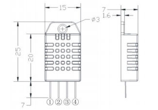
  • Preface
  • Chapter 1 The Raspberry Pi Pico – Before We Begin
  • Chapter 2 Getting Started
  • Chapter 3 Getting Started With The GPIO
  • Chapter 4 Simple Output
  • Chapter 5 Some Electronics
  • Chapter 6 Simple Input
             Extract: Simple Input 
  • Chapter 7 Advanced Input – Events and Interrupts
  • Chapter 8 Pulse Width Modulation
             Extract: PWM 
  • Chapter 9 Controlling Motors And Servos
             Extract: DC Motors
  • Chapter 10 Getting Started With The SPI Bus
  • Chapter 11 A-To-D and The SPI Bus ***NEW!
  • Chapter 12 Using The I2C Bus
  • Chapter 13 Using The PIO   
  • Chapter 14 The DHT22 Sensor Implementing A Custom Protocol
             Extract: A PIO Driver For The DHT22  
  • Chapter 15 The 1‑Wire Bus And The DS1820
  • Chapter 16 The Serial Port
  • Chapter 17 Using The Pico W - WiFi
             Extract: HTTP Client 
  • Chapter 18 Asyncio And Servers
  • Chapter 19 Direct To The Hardware
             Extract: Direct To The Hardware

Also of interest:

Raspberry Pico File System

<ASIN:1871962803>

<ASIN:B0BR8LWYMZ>

<ASIN:187196279X>

<ASIN:B0BL1HS3QD>

In this chapter we make use of all the ideas introduced in earlier chapters to create a raw interface with the low-cost DHT11/22 temperature and humidity sensor. It is an exercise in implementing a custom protocol directly in MicroPython using bit banging and then using the PIO. Given the documentation advises against using it, you might be wondering why we start with bit banging? The answer is that bit banging is easier to debug and it is usually a good idea to implement it first if possible, if only to prove that the device in question works and you know how it works.

The DHT22

The DHT22 is a more accurate version of the DHT11 and it is used in this project. The software will work with both versions and also with the AM2302, which is equivalent to the DHT22.

Model AM2302/DHT22

Image result for site:i-programmer.info DHT22
Power supply 3.3-5.5V DC
Output signal digital signal via 1‑wire bus
Sensing element Polymer humidity capacitor
Operating range
humidity 0-100%RH;
temperature -40~80Celsius
Accuracy
humidity +-2%RH(Max +-5%RH);
temperature +-0.5Celsius
Resolution or sensitivity
humidity 0.1%RH;
temperature 0.1Celsius
Repeatability
humidity +-1%RH;
temperature +-0.2Celsius

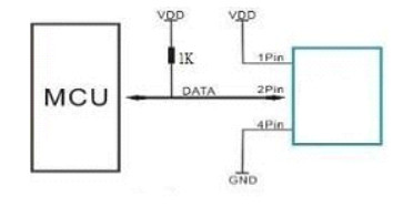
The device will work at 3.3V and it makes use of a 1‑wire open collector-style bus, which makes it very easy to make the physical connection to the Pico.
The 1-wire bus used isn't standard and is only used by this family of devices, so we have little choice but to implement the protocol in MicroPython.

Image result for site:i-programmer.info DHT22
The pinouts are:

  1. VDD

  2. SDA serial data

  3. Not used

  4. GND

and the standard way of connecting the device is:

Image result for site:i-programmer.info DHT22
Although the recommended pull-up resistor is 1K, a higher value works better with the Pico - typically 4.7K, but larger will work.

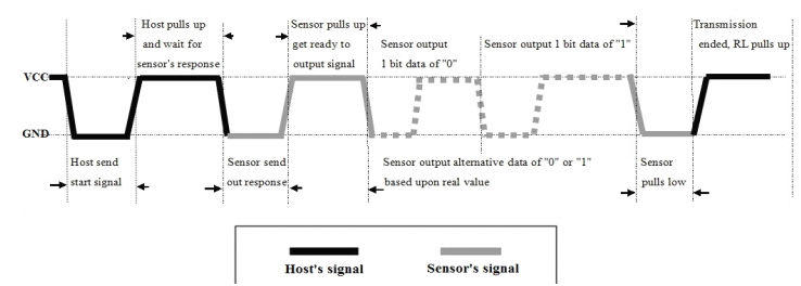
The serial protocol is also fairly simple:timing

  1. The host pulls the line low for between 0.8ms and 29ms, usually 1ms.

  2. It then releases the bus which is pulled high.

  3. After between 20µs and 200µs, usually 30µs, the device starts to send data by pulling the line down for around 80µs and then lets it float high for another 80µs.

  4. Next 40 bits of data are sent using a 70µs high for a 1 and a 26µs high for a 0 with the high pulses separated by around 50µs low periods.


What we have to do is pull the line low for 1ms or so to start the device sending data and this is very easy. Then we have to wait for the device to pull the line down and let it pull up again for about 160µs and then read the time that the line is high or low 40 times.

A 1 corresponds to 70µs and a 0 corresponds to 26 to 28µs. This is within the range of pulse measurements that can be achieved using standard library functions. There is also a 50µs low period between each data bit and this can be used to do some limited processing. The time between falling edge transitions is therefore 120µs for a 1 and 76µs for a 0.

When trying to work out how to decode a new protocol it often helps to try to answer the question, “how can I tell the difference between a 0 and a 1?”

If you have a logic analyzer it can help to look at the waveform and see how you work it out manually. In this case, despite the complex-looking timing diagram, the difference comes down to a short versus a long pulse!


Last Updated ( Monday, 17 May 2021 )