| Exploring Edison - Beyond mraa |
| Written by Harry Fairhead | ||||
| Monday, 02 May 2016 | ||||
Page 2 of 3
Example - toggling a lineAs an example consider the following C program which sets gpio-44 to output and then toggles it high and low as fast as possible:
Notice the "clever" use of sprintf to create strings which incorporate the number of the gpio line you are using. It you try this this out you will discover that the pulse train has a frequency of 50KHz and a pulse width of 10 microseconds. Which is comparable to mraa in non-memory-mapped mode.
So there is little to be gained from using Sysfs in this way - it is more a matter of knowing it is there. It is worth knowing that if you plan to read a gpio line using this technique after the first read you need to position the file pointer back to the start of the file to read subsequent values: lseek(fp, 0, SEEK_SET); Controlling the GPIO ModeIn principle you should be able to set the output mode of the GPIO lines using mraa but at the moment you can't and mraa wound not support the full range of possibilities even if it did work. There should be additional folders in the sys/class/gpio directories that allow you to control the configuration of the gpio line - pullup, pulldown etc. but these aren't present. Instead there are directories in sys/kernel/debug/ that do the same job. Why they are in the debugfs is not clear as they are generally useful and not particularly to do with debugging. The debugfs is usually not enabled in Linux and you have to recompile the kernel to enable it, but it is enabled in the standard distribution of the Edison firmware. If you get a list of all the folders in sys/kernel/debug/gpio_debug you will see that there is a folder for each gpio line. If you list all the folders in one of these, for example:
you will see a the following list of folders that relate to the configuration of the pin:
You can see that they are mostly in current and available pairs. The contents in current give you the value already in set and those in available give you the possible values you can set. Three of the files relate to the mode of operation of the pin:
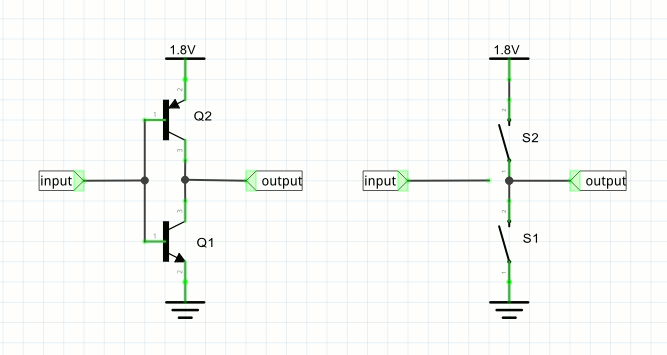
The current values of these are pullup 50k and disable. You might at this point think that this means that the default gpio pin configuration is 50K pullup but it isn't. The fact that open_drain is disabled sets the pin into pushpull output mode and the pullup and 50k are ignored. If you want to experiment setting the output modes then you can use cat and echo at the command line, but you need to know that if you make use of the Sysfs system to change the state of the gpio line then the mode is set back to pushpull automatically. This is presumably why mraa's mode setting function seems not to work. It isn't difficult to write some functions that let you set the output mode of a pin. The Output ModesBefore we get to the code to do the job it is worth spending a moment explaining the three basic output modes. In pushpull mode two transistors of opposite polarity are used, for example:
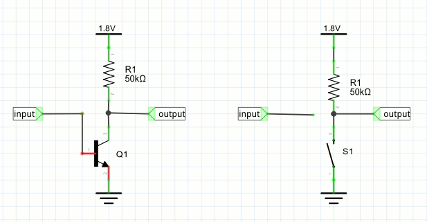
The circuit behaves like the two-switch equivalent shown on the right. Only one of the transistors, or switches is "closed" at any time. If the input is high then Q1 is saturated and the output is connected to ground - exactly as if S1 was closed. If the input is low then Q2 is saturated and it is as if S2 was closed and the output is connected to 1.8V. You can see that this pushes the output line high with the same "force" as it pulls it low. The Edison can source or sink up to 2mA. The pullup mode replaces one of the transistors by a resistor:
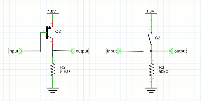
In this case the circuit is equivalent to having a single switch. When the switch is closed the output line is connected to ground and hence driven low. When the switch is open the output line is pulled high by the resistor. You can see that in this case the degree of pulldown is greater than the pullup, where the current is limited by the resistor. The advantage of this mode is that it can be used in an AND configuration. If multiple gpio or other lines are connected to the output, then any one of them being low will pull the output line low. Only when all of them are off does the resistor succeed in pulling the line high. This is used, for example, in a serial bus configuration like the I2C bus. Finally the pulldown mode is exactly the same as the pullup only now the resistor is used to pull the output line low:
In the case of the pulldown mode the line is held high by the transistor but pulled low by the resistor only when all the switches are open. Putting this the other way round - the line is high if any one switch is closed. Generally speaking the pushpull mode is best for driving general loads, motors, LEDs, etc. The pullup/down modes are used where you need to create a serial bus of some sort or when the load needs this sort of drive. |
||||
| Last Updated ( Sunday, 08 May 2016 ) |


