
| ESP32 In MicroPython: GPIO |
| Written by Harry Fairhead & Mike James | |||||||||||||||
| Monday, 18 December 2023 | |||||||||||||||
Page 1 of 2 GPIO is fundamental to connecting with the outside world. This extract from Programming the ESP32 in MicroPython, part of the I Programmer Library, shows you how to get started with GPIO. Programming the ESP32in MicroPython
|
|
GPIO0 |
Used at boot to signal Firmware upload |
|
GPIO1 |
Used for USB serial Tx |
|
GPIO2 |
Sometimes used to drive onboard LED |
|
GPIO3 |
Used for USB serial Rx |
|
GPIO6-11 |
Shared with Flash memory |
|
GPIO16-17 |
Not available on WROVER modules |
As is the case with most microprocessors, each GPIO line has multiple uses as you can see in the diagram (ESP32):
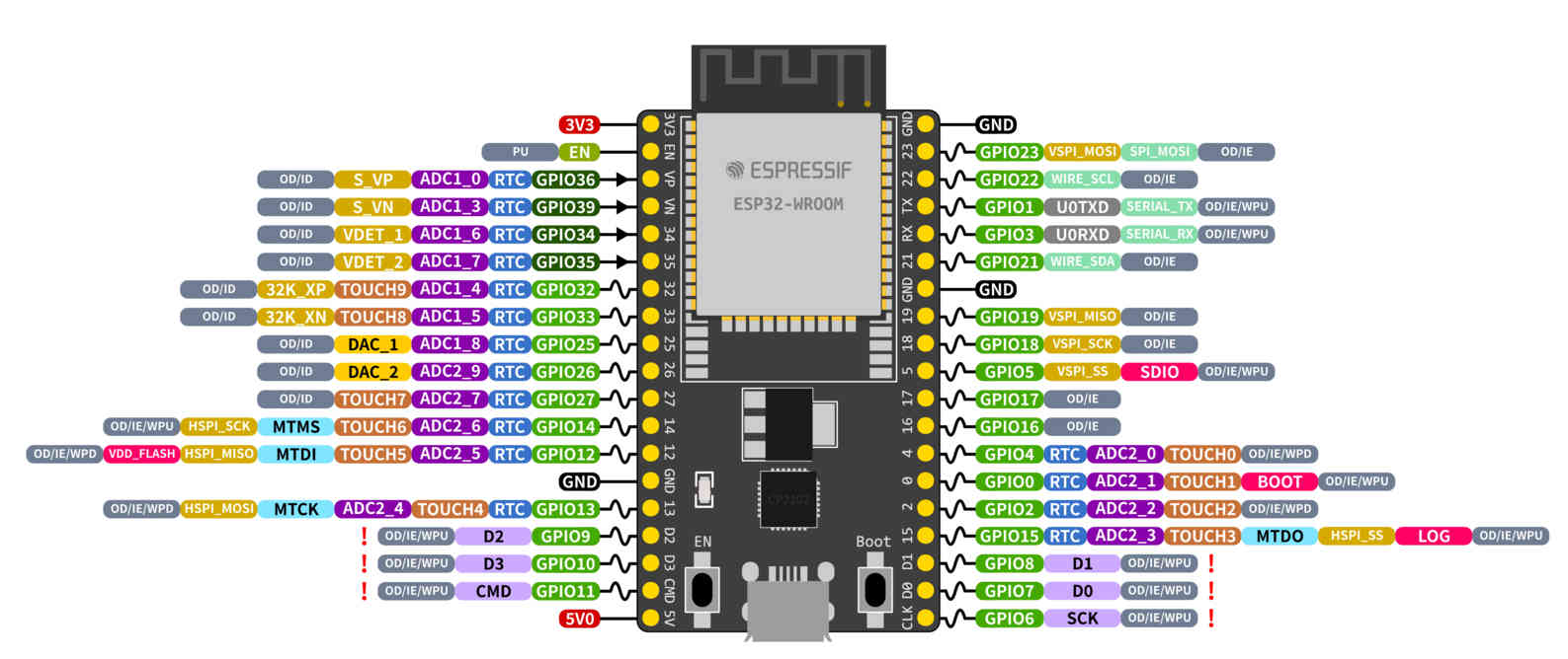
There are similar diagrams for the ESP-S2 and ESP-S3 development boards – to see the fine details of this diagram view the image on the book’s web page at www.iopress.info.
You can select what mode a pin is used in and in this chapter we concentrate on using pins in the simplest GPIO mode. Even so, which pins you select for general-purpose use should take into account what other uses you might put pins to.
In general you can use pins GPIO4, 5, 13 - 33 for general I/O and pins GPIO34-39 for input only. GPIO2 can also be used for general I/O if it isn’t connected to an onboard LED.
Another complication is that some pins are used when the ESP32 boots to set its state. Pins GPIO0, GPIO2, GPIO12 and GPIO15 are “Strapping Pins” and if you use pull-up or pull-down resistors to set their initial state you will change the behavior of the ESP32 when it boots.
Pins GPIO1, GPIO3, GPIO5, GPIO14 and GPIO15 are also used by the system at start up to send boot status data. This means that on boot these pins change state rapidly and could trigger any devices connected to them leading to difficult to find bugs.
Notice that, unlike when programming directly to the hardware, MicroPython doesn’t use the idea of setting the GPIO pin into a particular mode. Instead it provides classes that make use of GPIO pins in particular ways. For example, if you were programming directly to the hardware you would first set the pins you wanted to use to the mode you wanted to use, e.g. PWM (Pulse Width Modulation) and then you would start working with PWM operations. In MicroPython you would simply create a PWM object using the pin in question and expect it to take care of setting the pin to the correct mode. Notice, however, that you are still restricted to using pins that support the mode you are using.
There is no standard notation for which physical pin to connect to, but if the development board is based on the ESP32-DevKitC or similar the two connectors on either side are called J2 and J3 and the pins are numbered sequentially:
