| Inside the KML Placemark |
| Projects | |||||||
| Written by Mike James | |||||||
| Tuesday, 05 October 2010 | |||||||
Page 4 of 6

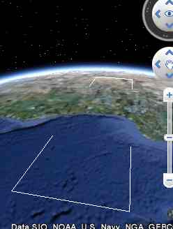
3D concernsSo far we have made use of 3D positioning in terms of x,y,z co-ordinates. If you want to you can work with just 2D co-ordinates x and y and leave z to be set to zero by default. This makes good sense when working with an essentially 2D mapping system like Google Maps rather than Google Earth. However when working with a true 3D system there are some slight differences. There is a problem of how to interpret any height that you specify - even if it is zero. You can use <altitudeMode> to mean ignore z and draw on the ground which is also the default action <altitudeMode> to mean z is the height above the local ground level and <altitudeMode>absolute</altitudeMode> makes z height above sea level. The other matter is that your points may well be on the surface of the earth but any line that you draw between them might go underground for some distance because of the curvature of the earth.This is usually only visible when you take an oblique view of the lines:
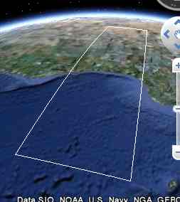
If you want to keep your lines on the surface then you need to add <tesselate>1</tesselate> so that lines follow the surface of the land or sea depending on the setting of the altitude mode.
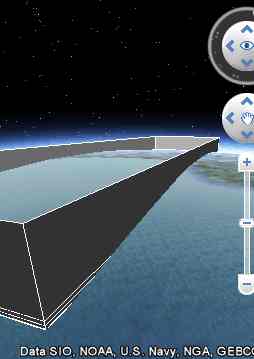
Finally there is the extrude property which can be turned on (1) to draw a "curtain wall" down from any line or polygon outline to the ground, sea or center of the earth. <extrude>1</extrude> Of course this only makes sense if you don't clamp the points to the ground i.e. you have to use either relativeToGround or absolute to position the points above the surface of the earth. If you try this out on the very large rectangle that we have been using as an example you will discover that to avoid intersecting the lines with the curvature of the earth the points have to be very high - about 10km. <Placemark> Notice that in this case you can see that the lines are straight and the intersection of the extruded "walls" with the earth's surface are curved.
The tessellation option doesn't make the lines drawn between the points follow the curve of the earth even though you will see the tessellate tag used in many examples that involve extrude - it is just ignored. If you want to draw extruded lines that follow the curvature of the earth you simply have to break the lines up into shorter segments.
<ASIN:0470095288> <ASIN:0321525590> <ASIN:0471790095> <ASIN:0470381248> <ASIN:1430216204> <ASIN:1419689037> <ASIN:0596101619> |
|||||||
| Last Updated ( Tuesday, 05 October 2010 ) |